
Table of Contents
Hardware Description
The new chassis manager uses a completely new set of hardware compared to the older revisions. The design is based around the Lantronix XPort AR module, along with accompanying external hardware for interface to the node. The SDK for this device allows the implementation of custom code which is used to interface and understand CMC instructions. A full schematic of the CM3 is attached as a PDF to this page.
Major Hardware Components
Lantronix XPort AR
")
The Xport AR is an embedded device server, produced by Lantronix. It runs off of the Evolution OS®, combined with the custom software written using the Xport AR SDK. The Xport AR acts as the 'brains' of the CM3, handling all the networking tasks, as well the link between the CMC instruction commands, and the physical interface to the node. It has the following basic features:
| Architecture | |
| CPU | Based on the DSTni-EX enhanced 16-bit, 120MHz x86 Architecture |
| Memory | 1.25 MB RAM and 4 MB FLASH |
| Firmware | upgradeable via FTP,TFTP, Serial Ports, Internal Web Server |
| Diagnostics | Built in diagnostics and comprehensive statistics |
| Network Interface | |
| Interface | Ethernet 10Base-T or 100Base-TX (Auto-Sensing) |
| Connector | RJ45 |
| Layer 3 Protocols | TCP, UDP, IP, ARP, ICMP, SSH, SSL, XML, HTTP, PPP, PAP, CHAP, DNS, SMTP, RSS, DHCP, BOOTP, AutoIP, SNMP, FTP, TFTP, Telnet, CGI |
| Serial Interface | |
| Interface | CMOS (Asynchronous, 5V Tolerant) |
| Data Rates | 300 bps to 230,400 bps (selectable by 1bps increments) |
| Characters | 7 or 8 data bits |
| Parity | Odd, even, none |
| Stop Bits | 1 or 2 |
| Control Signals | RTS, CTS, DSR, any PIO |
| Flow Control | XON/XOFF, RTS/CTS, User Selectable Characters |
The GPIOs are used to control the solid state relays used to power the node on/off and reset the node, as well as monitor the 'hardware status', see the next section for details on this.
")
More information on the Xport AR can be found here, and documentation on the device can be found here.
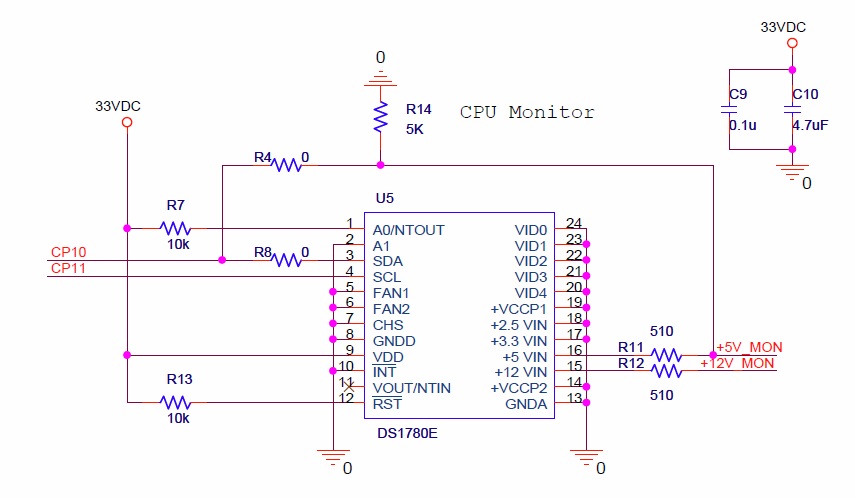
Voltage Monitor
The CM3 has a PC voltage monitoring chip installed, the DS1780E. This chip monitors the +5V, +12V, and temperature of the air in the case. The voltage levels are taken from the floppy connector (J2) which feed directly into the chip and communicates that information over I²C to the Xport AR. However the I²C is not active on the Xport AR, and so there is no way to effectively get accurate voltage and temperature data about the node.
The 'status' (i.e. on or off) of the node depends on the voltage levels of the power supply (PS), so as a work around for the lack of I²C support the current hardware version of the CM3 has the 5V line feed directly into one of the GPIO (set as an input) and if that is high the PS is on, and so the node is also on. Hopefully I²C will get some support in the future from Lantronix. Presently R4 and R14 is installed and R8 is left open. If I²C is to be implemented then R4 and R14 would have to be removed by hand, and R8 installed.
The functional block diagram and schematic implementation of the DS1780E are presented here:
") | ")
|
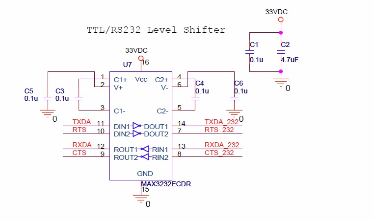
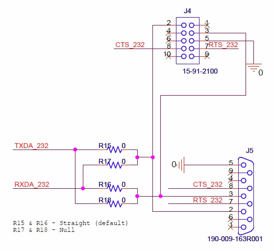
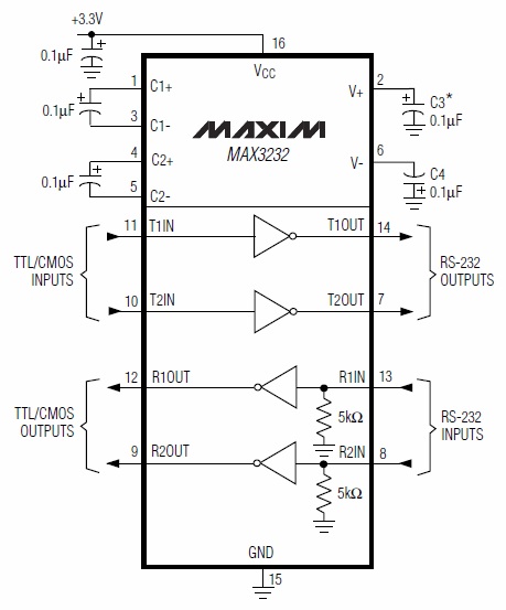
RS232 Level Shifter
The RS232 level (MAX3232) shifter takes the TTL compliant voltage levels from the Tx and Rx lines of the Xport AR and converts them to RS232 voltage standards (and vice versa). there is also 2 sets or resistors R15 & R16, and R17 & R18, which correspond to build in crossover or straight through signals. If R15 and R16 are installed then a straight cable is used to connect to the node serial port and if R17 and R18 are installed a null modem (or crossover) cable must be used. This is the sase for revision 4 of the CM3 board, the previous revision 3 had rotary switches rather than 0 ohm resistors. Also note that presently the RTS and CTS signals have to be shorted manually on the 5x2 100mil header in order for serial redirection to work. This was an oversight in the design and will be fixed in the next run.
") | ")
|
")
|
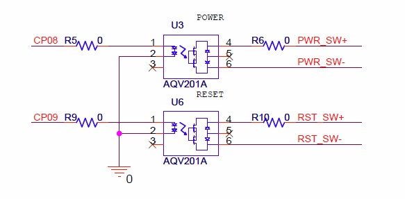
Solid State Relays
There are two solid state relays (AQV201A) that act as an intermediary to simulate the button press corresponding to a reset and power button for the node motherboard. Important to note, is that the power and reset commands will not work is one of the two output sides of the relays is ties to power or ground, it must be a floating power/closed, and not shorting one pin to ground.
")
Extra Parts
| Part Desc. | Manuf. | Part Number | Link |
| Power Connector | TE Connectivity | 179228-2 | link |
| Power Connector Pins | TE Connectivity | 179227-1 | link |
| DB9 Ribbon Connector | Amphenol Commercial Products | L17DEFRA09S | link |
| Rectangular Ribbon Connector | TE Connectivity | 1658620-1 | link |
| Right angle brackets | Keystone Electronics | 621 | link |
| Jumper Cables (power/reset) | Sparkfun | PRT-10367 | link |
| 4-40 flat screw | McMaster Carr | 91500A122 | |
| 4-40 Pan Head Screw | McMaster Carr | 91735A101 |
Notes on latest delivered run
REMOVE the following 0 ohm resistors: R6, R7. They are located under the MAX3232EC chip.
Attachments (9)
-
SCHEMATIC1 _ Xport.pdf
(25.2 KB
) - added by 13 years ago.
Schematic of CM3
-
CM_232.jpg
(57.3 KB
) - added by 13 years ago.
RS232 Level shifter (schematic)
-
CM_232_2.jpg
(51.6 KB
) - added by 13 years ago.
RS232 Connections (schematic)
-
CM_Relay.jpg
(34.3 KB
) - added by 13 years ago.
Solid State Relays (schematic)
-
CM_Monitor.jpg
(75.1 KB
) - added by 13 years ago.
Hardware Monitor (schematic)
-
CM_Xport.jpg
(87.8 KB
) - added by 13 years ago.
Xport AR (schematic)
-
xport_ar.jpg
(6.7 KB
) - added by 13 years ago.
Xport AR (image)
-
DS1780E.gif
(21.2 KB
) - added by 13 years ago.
Hardware Monitor (block diagram)
-
CM_232_block.jpg
(51.4 KB
) - added by 13 years ago.
RS232 Level shifter (block diagram)
Download all attachments as: .zip