
| Version 5 (modified by , 13 years ago) ( diff ) |
|---|
Introduction
Table of Contents
The ORBIT Chassis Manager (CM) is a simple, reliable, platform-independent subsystem for managing and autonomously monitoring the status of each node in the ORBIT network testbed.
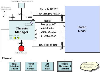
As shown in Figure 1, each ORBIT grid node consists of one Radio Node with two radio interfaces, two Ethernet interfaces for experiment control & data, and one Chassis Manager (CM) with a separate
 Ethernet network interface. The Radio nodes are positioned about one meter apart in a rectangular grid. Each CM is tightly coupled with its Radio Node host. CM subsystems are also used with non-grid support nodes. The CMC is the control and monitoring manager for all CM elements of ORBIT. An “Experiment Controller” (EC), also referred to as the “node handler”, is the ORBIT system component that configures the grid of Radio Nodes (through the CMC service) for each experiment. The non-Grid elements of the ORBIT lab are not normally in the management domain of the EC.
Each Chassis Manager is used to monitor the operating status of one node. It can determine out-of-limit voltage and temperature alarm conditions, and can regain control of the Radio Node when the system must return to a known state. Managing a system in this manner reduces the human resources needed to monitor hundreds of nodes. The CM subsystem also aids debugging by providing telnet to the system console of the Radio Node, as well as telnet access to a CM diagnostic console.
Requirements
The functional block diagram of the Chassis Manager is shown in Figure 1.

The Chassis Manager provides the following functions to remotely manage an associated Radio Node in the ORBIT grid, or a supporting non-Grid node:
- Issue a NMI system reset to the Radio Node: Upon receiving a “Radio Node Reset” command from the CMC, a local CM drives a signal appropriately to reset the Radio Node.
- Control the system power state of the Radio Node: Upon receiving a “Power On/Off” command from the CMC, a local CM drives a signal appropriately to power up or down the Radio Node. Since the same control line is used both for power on and off, the CM must verify the assumed state of the node before issuing the command.
- Obtain Chassis Status (Voltage, Temperature, and other status): The CM periodically reports node status to the CMC. This status message includes voltages, temperature, and other tbd parameters.
- Provide a pass-through Telnet session Radio Node: The CM provides a “pass-through” Telnet session to the serial console of the Radio Node Host. A workstation can create this connection by starting a telnet session to the IP address of the CM using port 3025. The Host serial port baud rate is stored in the NodeID box, and has the default value 115200 baud.
- Provide CM diagnostics: There are several diagnostic commands designed for integration and test. These include:
- Remotely identify a CM from the CMC: An “Identify” command issued from the CMC causes the CM to blink a local highly-visible “Identify LED” twice/second for approximately a 20 second period.
- Identify a node at the CMC from the CM: A momentary contact button on the Grid Node Chassis generates an IDENTIFY message to the CMC. The CMC then blinks the Identify LED at a high rate for approximately two seconds. This assists in physical verification of node placement and a quick test of end-to-end connectivity with the CMC.
- Provide a Telnet session to the CM console: The CM provides a “pass-through” Telnet session to the serial console of the CM. A device can create this connection by starting a telnet session to the IP address of the CM using port 23. The Telnet session and the directly RS232 connected 57600 baud console session provides a menu driven interface to control CM functions. A sample of the menu driven CM console session is shown in Figure 2.
- Provide a means to reset (reboot) the CM (both locally and remotely): The CM accepts a reset command from a momentary contact push button switch on the CM, a push button switch on the NodeID box, or from a “console” session directly connected or through a telnet session.
- Provide a means to locally interrogate the Grid Position of the node: The identity of the CM is determined by reading the “grid position” from the NodeID box EEPROM. This “grid position” is the either the x,y coordinate of the node, or the ID number of a non-Grid node. The “grid position” is used to create the static IP address of the CM.. The static IP address space of the ORBIT system is defined in Table 1 below.
| Static IP Address | Component |
| 10.1.—-.—- | CM Grid and non-Grid components |
| 10.1.x.y | Main grid coordinate (x,y) |
| 10.1.100+N,x|y | Sandbox Grid N and coordinate (x,y) |
| 10.1.100.y | Support Grid node y |
| 10.1.200.1 | Chassis Manager Controller |
| 10.1.222.222 | Error default CM address |
| Table 1 Orbit Static IP Address Space |
- Provide local visual indication of node operational status: The CM provides an indicator that the CM is running (a slowly blinking LED).
- Provide a control API to the Experiment Controller: The EC and CMC implement a management communications protocol to exchange command and status information. This protocol is defined later in this document.
All commands processed by the Chassis Manager Controller generate a reply message to indicate weather the command was executed successfully or not.