
| Version 4 (modified by , 16 years ago) ( diff ) |
|---|
The Aggregate SandBox Switch
The aggregate sandbox switch is a replacement for legacy sandbox switches for sb 1,2,5,6,7, and 8. Therefore it encompasses the VLANs required for all 6 testbeds to function.
Testbed switch layout
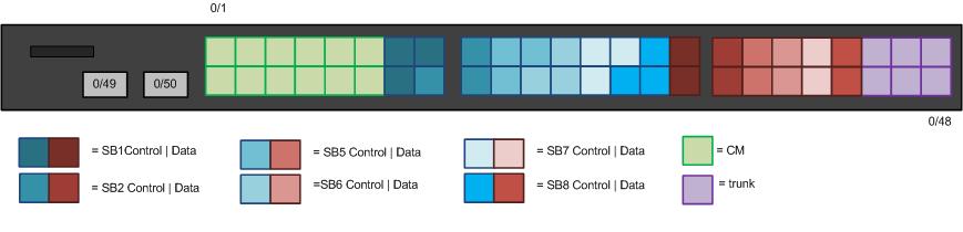
Each testbed requires 2 ports each for CM, Control, and Data links for the nodes, a Control VLAN link to the Console, and a trunk link to the top switch. As an OpenFlow switch, we also need a dedicated port to connect the switch to a controller. In the aggregate switch ports are allocated in the following numbers:
- CM: 12 ports (2 per SandBox)
- Control: 18 ports - 12 for nodes, + 6 for Console links
- Data: 12 (as with CM)
- !OpenFLow control VLANs: 2 (to controller - two to make things tidy)
- Trunk: 4 (leftover)
VLANs
VLAN 3 (CM) is consistent across all SandBoxes. Each sb has its own Control and Data VLANs as such:
| Testbed | Control VLAN | Data VLAN |
| sb1 | 11 | 12 |
| sb2 | 13 | 14 |
| sb5 | 19 | 20 |
| sb6 | 21 | 22 |
| sb7 | 23 | 24 |
| sb8 | 25 | 26 |
In addition, VLAN 100 is the defacto VLAN for the !OpenFLow control channel at WINLAB.
Port Assignments
The final port VLAN assignments:
| Port(s) | VLAN(s) | Description |
| 0/1-12 | 3 | CM |
| Control-to nodes | ||
| 0/13,14 | 11 | sb1_ctrl |
| 0/15,16 | 13 | sb2_ctrl |
| 0/17,18 | 19 | sb5_ctrl |
| 0/19,20 | 21 | sb6_ctrl |
| 0/21,22 | 23 | sb7_ctrl |
| 0/23,24 | 25 | sb8_ctrl |
| Control-to Consoles | ||
| 0/25 | 11 | sb1_ctrl |
| 0/26 | 13 | sb2_ctrl |
| 0/27 | 19 | sb5_ctrl |
| 0/28 | 21 | sb6_ctrl |
| 0/29 | 23 | sb7_ctrl |
| 0/30 | 25 | sb8_ctrl |
| Data | ||
| 0/31,32 | 12 | sb1_data |
| 0/33,34 | 14 | sb2_data |
| 0/35,36 | 20 | sb5_data |
| 0/37,38 | 22 | sb6_data |
| 0/39,40 | 24 | sb7_data |
| 0/41,42 | 26 | sb8_data |
| 0/43-48 | 1,3,11-14,19-26 | Trunk |
Legacy Configurations
All forms of spanning tree (STP, PVST+) are disabled for compliance with OpenFlow and Node-handler/Agent services. From configuration mode:
spanning-tree disable
no spanning-tree vlan 1,3,11-14,19-26
vlans are named from the vlan context.
Interface-range contexts are used for batch configuration of similar ports. Below is the configuration of the CM and SB1 Control VLAN ports:
!(config)# interface range gi 0/1-12
!(config-if-range)# switchport access vlan 3
!(config-if-range)# interface range gi 0/13-14
!(config-if-range)# sw acc vlan 11
Similarly, the trunk ports:
interface range gi 0/43-48
switchport mode trunk
switchport trunk allowed vlan 3,11-14,19-26
switchport trunk native vlan 1
OpenFlow configurations
To be added.
Attachments (1)
- sw-sb-01.jpg (22.5 KB ) - added by 16 years ago.
Download all attachments as: .zip