
| Version 29 (modified by , 9 years ago) ( diff ) |
|---|
Full-Duplex Wireless using USRP N210
Description
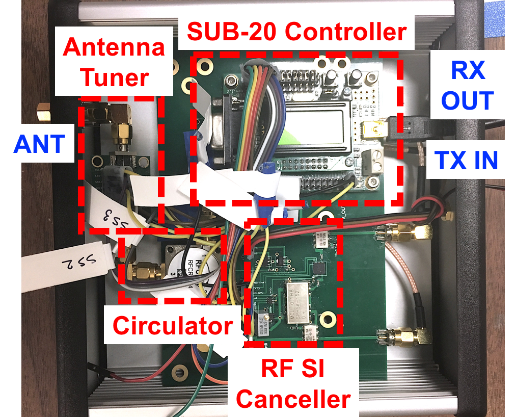
In this tutorial, we'll use node11-10 in the main grid (equipped with a USRP N210) to transmit and receive a single frequency over the air to demonstrate full-duplex wireless capability using the Columbia FlexICoN's Gen-1 Frequency-Flat Amplitude- and Phase-based RF Canceller. Pictures of the FlexICoN RF canceller and node11-10 in the main grid equipped with full-duplex capability are below:
Figure 1: The ORBIT-FlexICoN Full-Duplex Node 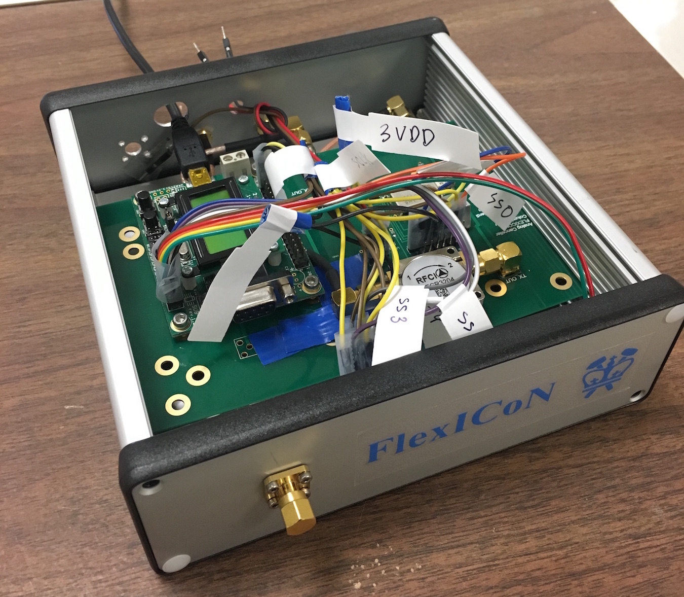
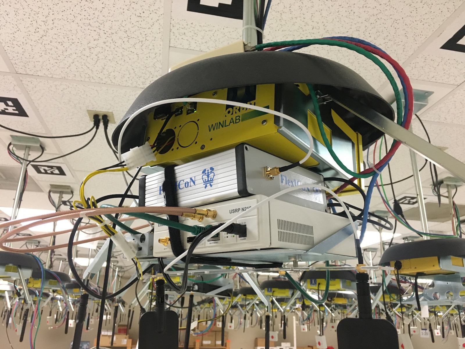
(a) The FlexICoN RF Canceller (b) Full-Duplex SDR at node11-10 in the ORBIT grid


For more information, please read:
T. Chen, J. Zhou, N. Grimwood, R. Fogel, J. Marasevic, H. Krishnaswamy, and G. Zussman, “Demo: Full-duplex Wireless based on a Small-Form-Factor Analog Self-Interference Canceller,” in Proc. ACM MobiHoc'16, 2016. (PDF) (DOI)
Please email Tingjun Chen (tingjun [at] ee.columbia.edu) if you are using (or plan to use) the full-duplex node, or if you have any questions. We also thank Mahmood Baraani Dasterjerdi and Steven Alfano for their great contributions.
Hardware / Software Resources Utilized
- USRP N210 with node11-10 in the ORBIT main grid
- SUB-20 is a multi-interface USB adapter for providing popular interfaces between PC (USB host) and different hardware devices. Specifically, we use the SUB-20 SPI module to control and configure the Gen-1 RF canceller (see Fig. 1(a)). The user manual can be found here.
- UHD is already installed with the imaged SDR node.
- The
Eigen C++Library is used for basic algebra used in channel estimation and digital self-interference cancellation. The Eigen releases can be found on the this website. We used the latest stable release Eigen 3.3.4 through our testings and experiments.
All the source code is also publicly available at here.
Set Up
Before you can access the testbed, you need to make a reservation and get it approved by the reservation service. After receiving the reservation's confirmation (approval) email:
- Login into reserved domain:
ssh username@conslole.grid.orbit-lab.org - Make sure that the full-duplex node is powered down for loading the desired image:
omf tell -a offh -t node11-10 - Load an image on the node (this process can take about a few minutes so please be patient):
omf load -i orbit-flexicon.ndz -t node11-10 - Turn on the node:
omf tell -a on -t node11-10 - Login into the node:
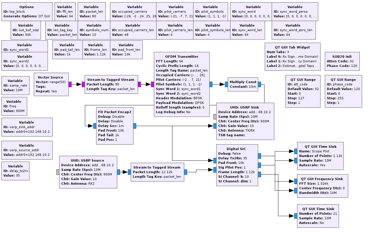
ssh root@node11-10After login into the node, aflexicon_orbitfolder should exist under the home directory ofnode11-10:~/which contains the source code of this example. You can always retrieve the most recently updated code from here.
Run the Experiments
You will need to login into the full-duplex node (by ssh root@node11-10) in two separate terminal windows lo for running the experiment: one for the main full-duplex transceiver UHD program and one for controlling the RF canceller
In Terminal 1 (UHD)
- Build the example:
cd ~/flexicon_orbit/fd_transceiver_simple/uhd/
mkdir build
cd build
cmake ../
make
- Check the conection and serial number of the USRP N210 at
node11-10:uhd_find_devices. The serial number should beF331D4. - Run the example with IQ rate
rate, carrier frequencyfreq, TX gaintx-gain, and RX gainrx-gain:./fd_transceiver_simple --tx-args="serial=F331D4" --rx-args="serial=F331D4" --rate 1e6 --freq 900e6 --tx-gain 10 --rx-gain 10
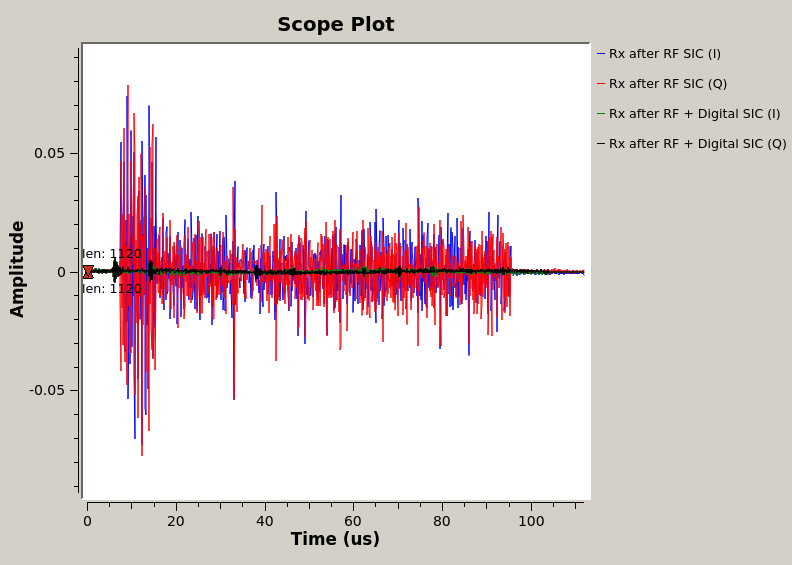
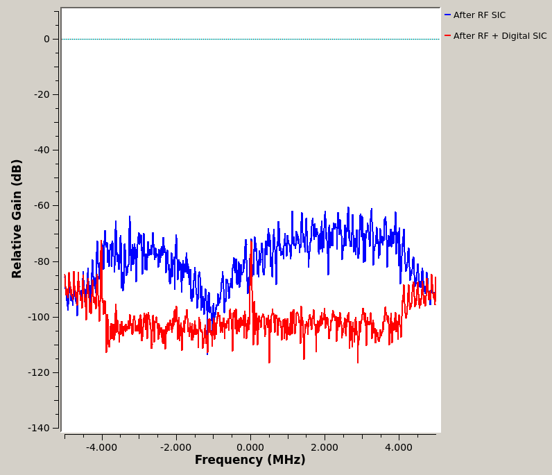
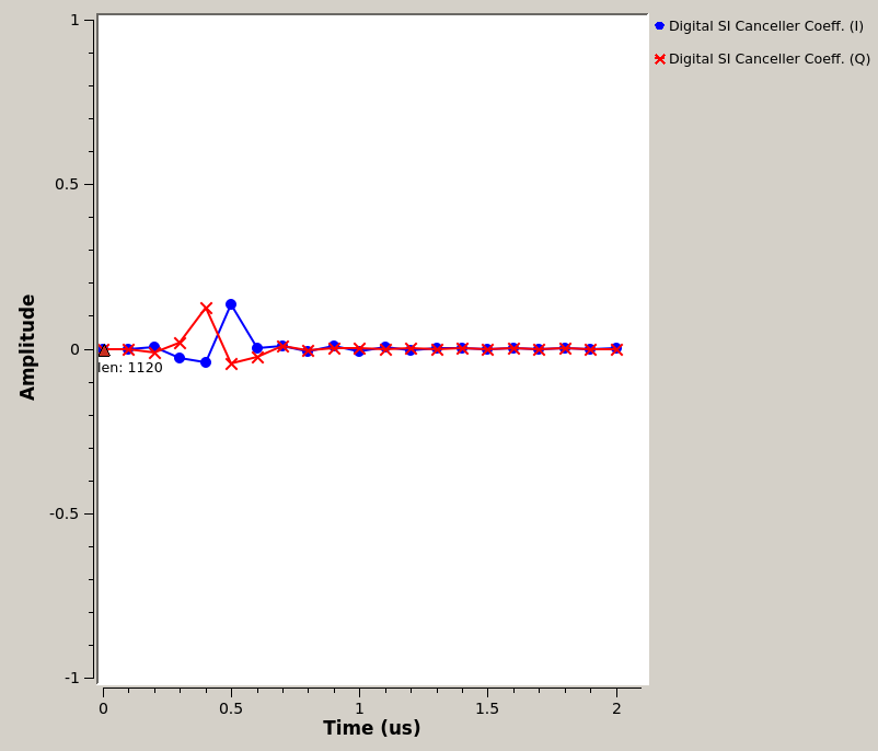
The default sine wave has an amplitudeampl = 0.3and wave frequencywave-freq = 100e3(100kHz). This terminal window will show the power level at RX baseband, after RF cancellation (before digital) and after digital cancellation, respetively.
In Terminal 2 (SUB-20)
- Build the RF canceller configuration code:
cd ~/flexicon_orbit/fd_transceiver_simple/sub20/
make
- Check the connection to the SUB-20 device:
lbusb. You should see a XDIMAX devices connected to the USB hub. - Program and configure the RF canceller with the desired values:
./rf_canc_config ATT PS C1 C2 C3In particular, theATT = 0, 1, 2, ..., 127andPS = 0, 1, 2, ..., 255codes are for configuring the 7-bit attenuator and 8-bit phase shifter of the Gen-1 RF canceller. It is recommended to useC1 = 16, C2 = 3, C3 = 9. You can play with the values ofATTandPSuntil you see good cancellation profile (e.g., low residual self-interference power level) in Terminal 1.
Attachments (7)
- FlexICoN-gen1-node11-10.jpg (614.4 KB ) - added by 9 years ago.
- FlexICoN-gen1-canceller.jpg (476.4 KB ) - added by 9 years ago.
- FlexICoN-gen1-canceller-label.png (1.2 MB ) - added by 8 years ago.
- flexicon_orbit_grc_ofdm_node.png (142.2 KB ) - added by 7 years ago.
- flexicon_orbit_grc_ofdm_node_tab0.png (103.1 KB ) - added by 7 years ago.
- flexicon_orbit_grc_ofdm_node_tab1.png (37.6 KB ) - added by 7 years ago.
- flexicon_orbit_grc_ofdm_node_tab2.png (35.1 KB ) - added by 7 years ago.