
| Version 11 (modified by , 15 years ago) ( diff ) |
|---|
Assembling the LV-67C based Node
The assembling of new LV-67C based orbit node can be broken down into 4 tasks.
Flash The LV67-C bios
You will need the USB Thumb drive which has the bios and the utility to boot the motherboard from.
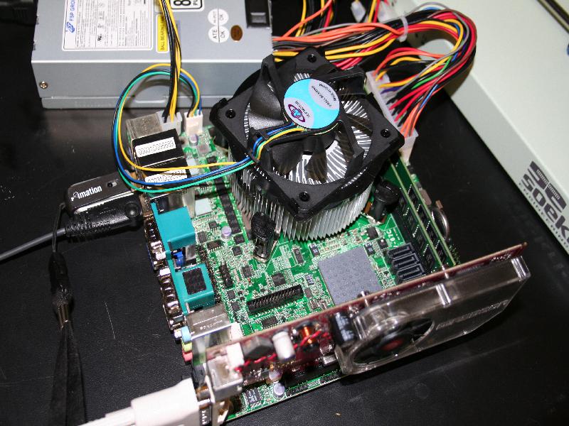
You will need a Video Card to flash the bios, the motherboard does not have one.
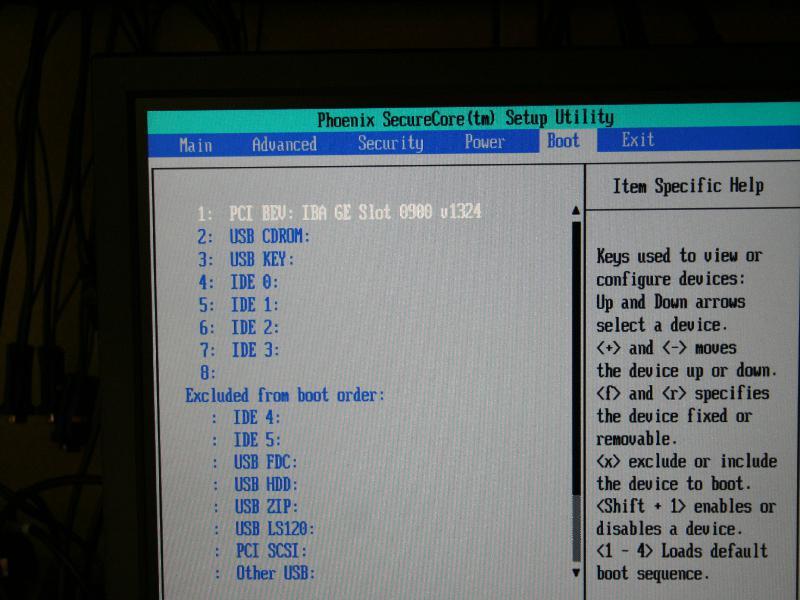
- Hit DEL key to get into BIOS
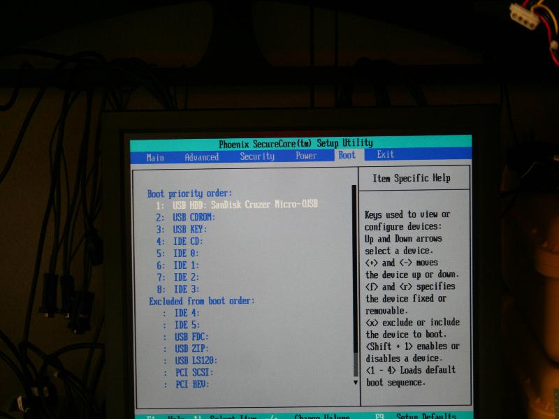
- change boot settings to boot of the USB Thumb drive.
- Reboot the Machine.
- Boot into the DOS shell.
- Change directory to bios
- Run plash16.exe bios.bak
How to flash and install the CM3 module
How to Assemble the Case
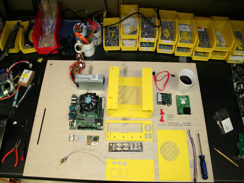
Components you will need to assemble a case:
System:
- 1 x LV-67C mother board
- 1 x 270 Watt power supply (Part Number FSP270-60LE)
- 1 x Sata Hard drive
- 1 x CM3
- requsite cables for CM3 ILYA FIX ME
- 1 x sata cable
- 1 x serial cable (from cm3 to motherboard)
Case:
- 1 x case Chassis (U shaped chassis)
- 1 x rear face plate cap (Folds over the U)
- 1 x front face plate (has cm3 punch outs, and hard dive mount holes)
- 1 x top cover (has Circular CPU ventilation holes)
- 1 x motherboard face plate (supplied with the motherboard)
- 1 x Velcro wire strap
Fasteners:
- 4 x 6-32 ½" 100 degree screws for securing the motherboard
- 12 x 6-32 ¼" 100 degree screws for fastening the case together and securing the power supply to the case
- 1 x 6-32 ¼" pan head screw for fastening the power supply.
- 3 x 6-32 3/16" 100 degree screws for CM mounting to chassis
- 3 x 6-32 9/32" hex stand offs for CM mounting
- 3 x 6-32 3/16" pan head screws for CM mounting
- 4 x M3 5mm stand offs for hard drive mounting
- 4 x M3 5mm screws for hard drive mounting
Wireless Adapters:
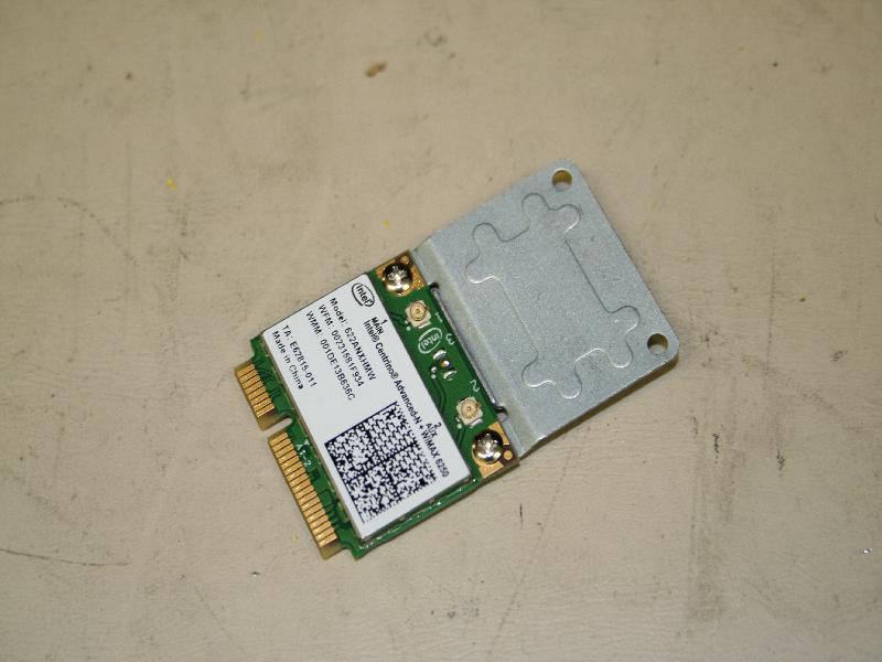
- 1 x minipcie Intel Wifi + Wimax 6250 card
- 1 x pcimcia Atheros Ar5212A 802.11 a/b/g wireless card
- 1 x minipice ½ height adapter
- 2 x minipice adapter screws (supplied with adapter)
- 3 x ufl-sma pig tails (9in)
Main U chassis:
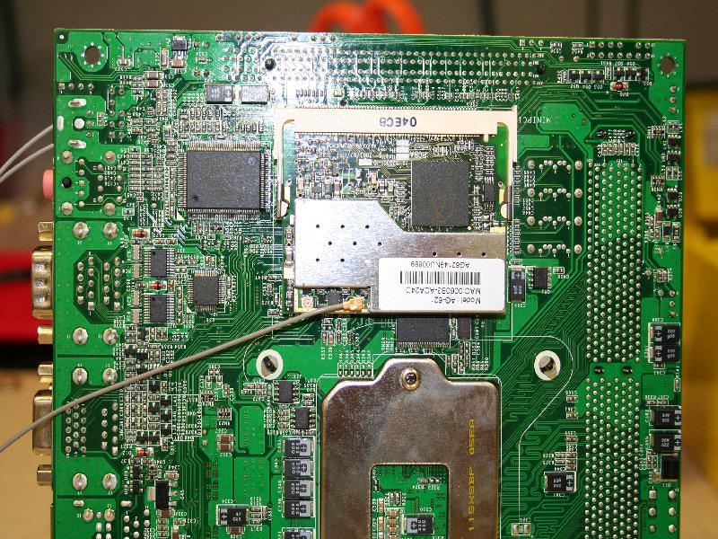
- Assemble the mother board:
- Attach the minicpie and pcimcia cards to the mother board.
- The mother board should come out of the static bag with cpu and memory installed.
- Connect all the pig tails and route the wires to the right side (facing the rear) of the motherboard.
- The Mother board should be aligned with the screw holes so that the headers point away from the vent hatching on the u channel.
- The orientation of the screw holes on the chassis is very specific.
- While aligning the mother board route the sma header from under neath the motherboard to the right behind the standoff.
- This keeps the sma-ufl wires away from the cpu fan.
- Once aligned use the ½" screws to secure the mother board.
- Attach the minicpie and pcimcia cards to the mother board.
- Install Power supply:
- The power supply sits in the open area to the left (looking at the rear) of the mother board.
- Separate the yellow/black 4 pin plug from the rest of the cables
- Slide in the power supply into place, while threading the black/yellow 4 pin header below the cpu heatsink.
- It's important to thread the wire below other wise it will get stuck in the cpu fan.
- The power supply will be secured to rear face plate when it is installed.
- The power supply is not attached to the main U chassis however it must be inserted before installing the rear cap.
- Connected the 24 pin atx power headers.
- Connect 4 pin plug it to the extra power header behind the PS/2 keyboard/mouse riser.
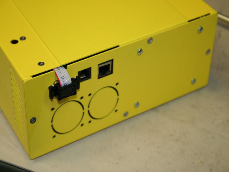
- Assemble the rear cap:
- Pass one end of the serial cable through the mother board face plate opening
- place the cable in the cut out on the top of the face plate opening.
- Attach the mother board face plate to the opening on the rear face plate cap, locking the serial cable into the designated opening.
- The face plate should be mount so that it is open on the right side (to allow for a expansion card) and closed on the left (as close to the power supply opening as possible).
- Mounting the rear cap on the U channel Chassis:
- Fasten the rear cap with 2 of the 6-32 ¼" 100 degree screws on the bottom of the U chassis.
- Use two of 100 degree screws and attach the bottom holes power supply to the rear cap.
- Use the 6-32 ¼" pan head screw to fasten the top of the power supply (near the 3 prong power header) to the rear cap.
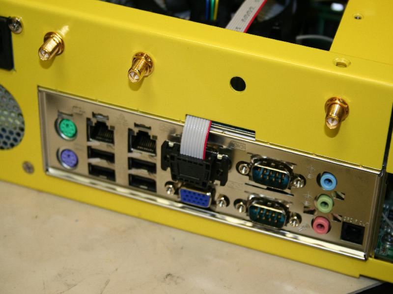
- Bolt all the sma headers to the face plate. The header position convention used is:
- Header 1 of the wimax card goes to the left most (closest to the power supply) hole.
- Header 2 immediately to the right of header 1.
- WiFi header of the 802.11 card goes to the right most hole.
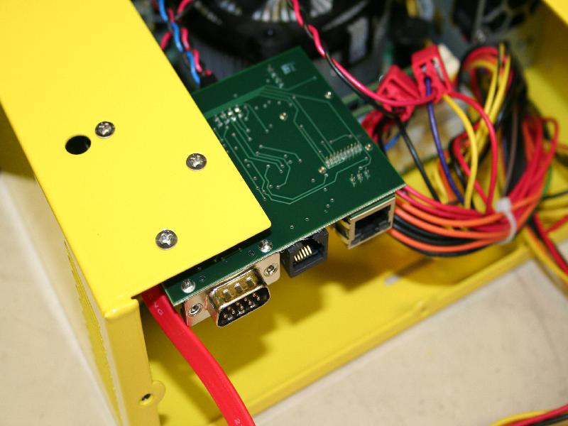
- Mounting the CM:
- Attach the 3 6-32 hex stand offs to the cm card with the 3 6-32 pan head screws
- thread the other end of the serial cable between the 3 stand offs
- align the 3 stand offs with the 3 triangle oriented holes on the front left corner of the top of the U chassis.
- use the 3 3/16" 100 degree screws to attach the cm to the U chassis
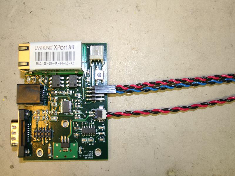
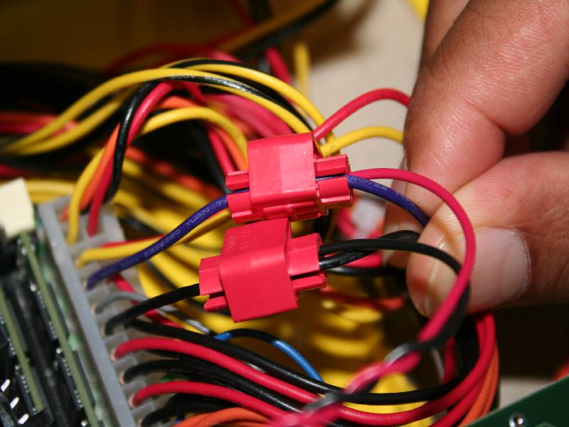
- Wiring the CM:
- ILYA FIX ME
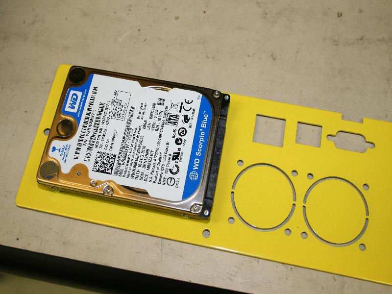
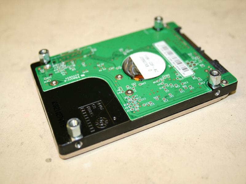
- Attach and Wire the hard drive:
- attach the M3 5mm hex stand offs to the hard dive using the bottom holes.
- Align the female end of stand offs with the holes on the right side of the front face plate (facing front)
- The face plate should be oriented so that the cm holes are in the upper left corner.
- The drive should be on the "inside" of the chassis and sata header should point to the left (towards the center of the case).
- Fasten the disk, stand off assembly to the face plate with the M3 5mm pan head screws.
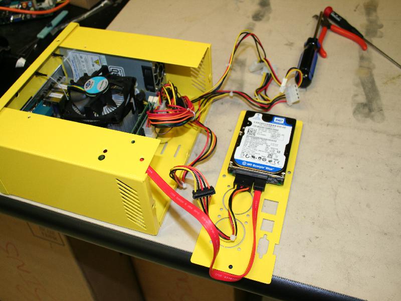
- Attach power and sata cables to the drive. 1.When attaching the sata cable to the mother board, use the header closest to the CPU (sata1)
- loop the velcro strap through the holes on the bottom:
- Tie down all the loose wires. 1.This prevents stray wires from getting to close to the cpu fan.
- Mount the rear face plate:
- Use the three 6-32 ¼" 100 degree screws to attach the front face.
- use only the 2 side and bottom screw holes
- the top of the face plate will be attached to the top cover
- Use the three 6-32 ¼" 100 degree screws to attach the front face.
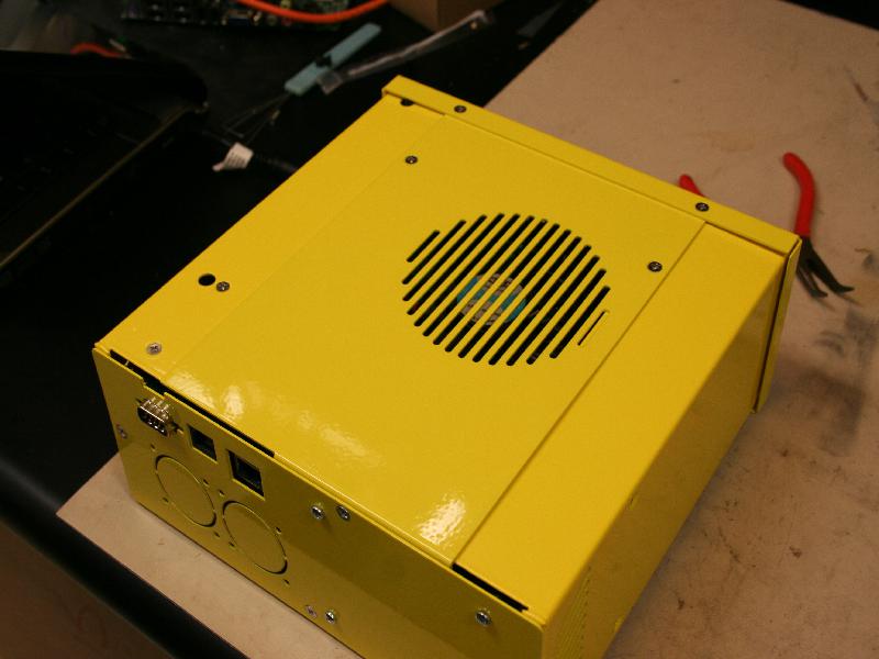
- Attach the Top Cover
- Use the remaning screws to attach the top cover.
- The rear of the top cover should go below the cap.
Attachments (25)
-
AttachVideo.jpg
(115.8 KB
) - added by 15 years ago.
Attaching Video Cable
-
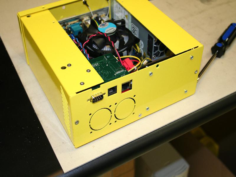
BackPlate.jpg
(71.3 KB
) - added by 15 years ago.
Installed Back Plate
-
BootSequence.jpg
(77.5 KB
) - added by 15 years ago.
Bios Boot Sequence Screen
-
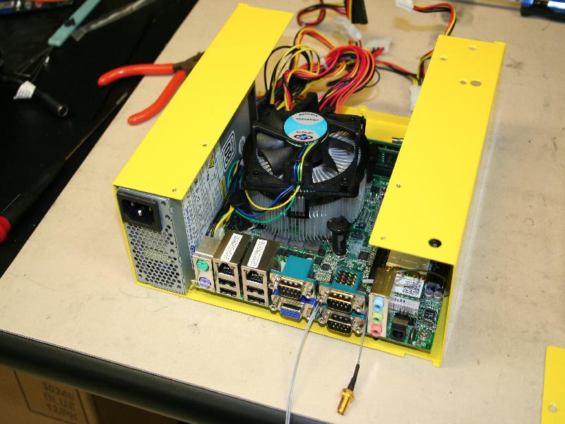
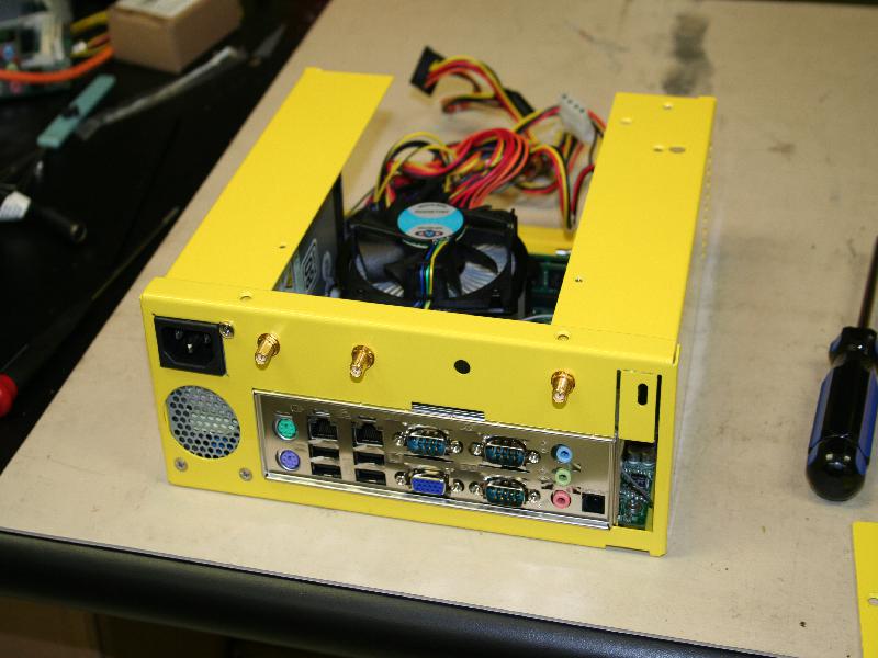
CasePowerMotherB.jpg
(91.1 KB
) - added by 15 years ago.
Mother Board and Power Supply Installed in U Channel
-
CmMount.jpg
(69.2 KB
) - added by 15 years ago.
Mounted CM
-
CmWire.jpg
(98.1 KB
) - added by 15 years ago.
Wiring of the CM
-
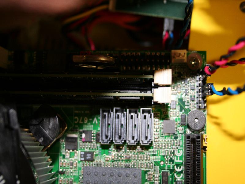
CmWireMotherB.jpg
(79.6 KB
) - added by 15 years ago.
Cm Wires attached to the motherboard
-
ComponentList.jpg
(103.2 KB
) - added by 15 years ago.
List of Components
-
DiskBackPlate.jpg
(85.6 KB
) - added by 15 years ago.
Disk attached to Back Plate
-
DiskStandOff.jpg
(65.6 KB
) - added by 15 years ago.
Standoffs mounted to disk
-
DiskWire.jpg
(84.8 KB
) - added by 15 years ago.
Wiring of Disk to Motherboard
-
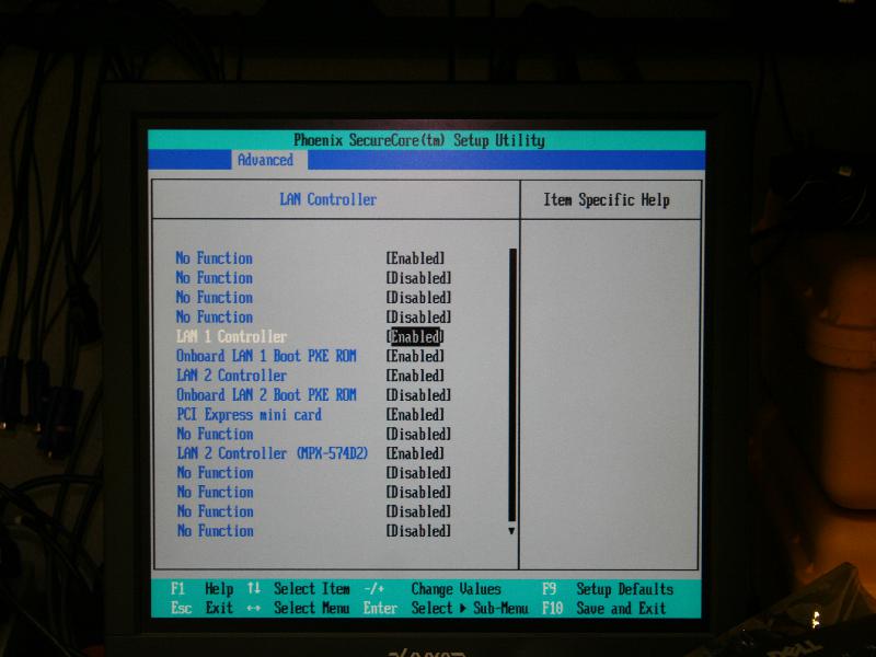
EnableLan.jpg
(63.8 KB
) - added by 15 years ago.
Enable the Lan Rom
-
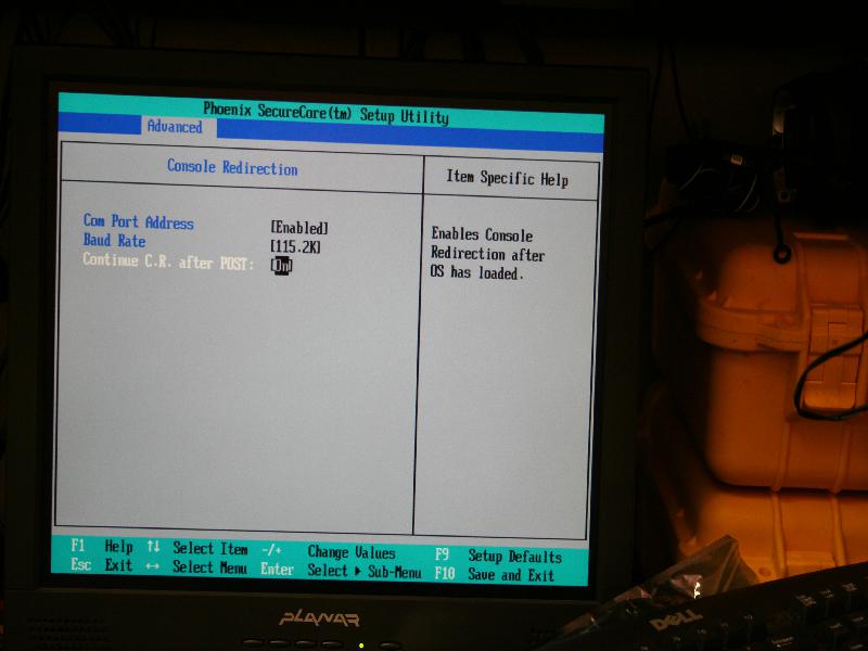
EnableSerial.jpg
(57.1 KB
) - added by 15 years ago.
Enable Serial Console Redirection
-
FrontFace.jpg
(74.1 KB
) - added by 15 years ago.
Attached Front Face
-
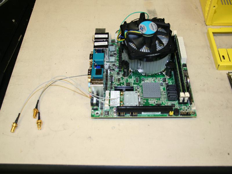
MBoardAssembled.jpg
(73.2 KB
) - added by 15 years ago.
Motherboards with Wireless Cards and UFL headers
-
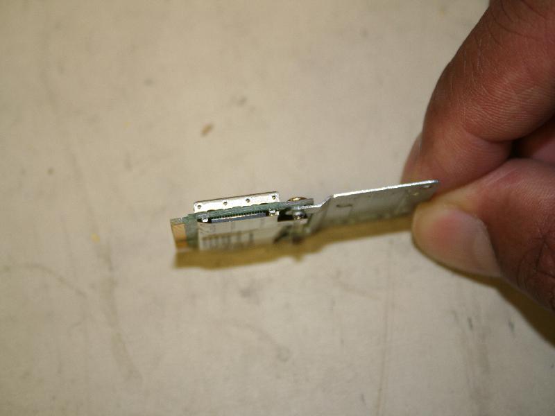
PciESide.jpg
(41.6 KB
) - added by 15 years ago.
Top profile of ½ Height Pcie Card with Extender attached.
-
PciETop.jpg
(64.8 KB
) - added by 15 years ago.
Side profile of ½ Height Pcie Card with Extender attached.
-
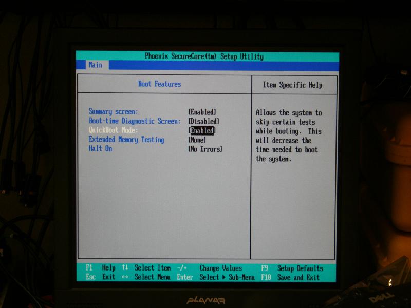
QuickBoot.jpg
(56.3 KB
) - added by 15 years ago.
Disable Halt on Errors
-
SerialBack.jpg
(45.9 KB
) - added by 15 years ago.
Serial cable attachment back
-
SerialFront.jpg
(69.5 KB
) - added by 15 years ago.
Serial cable attachment front
-
TopCover.jpg
(62.7 KB
) - added by 15 years ago.
installed Top Cover
-
UflAttachBottom.jpg
(173.1 KB
) - added by 15 years ago.
Attaching Bottom UFL cable
-
VampClip.jpg
(80.4 KB
) - added by 15 years ago.
Vampire Clips Installation
-
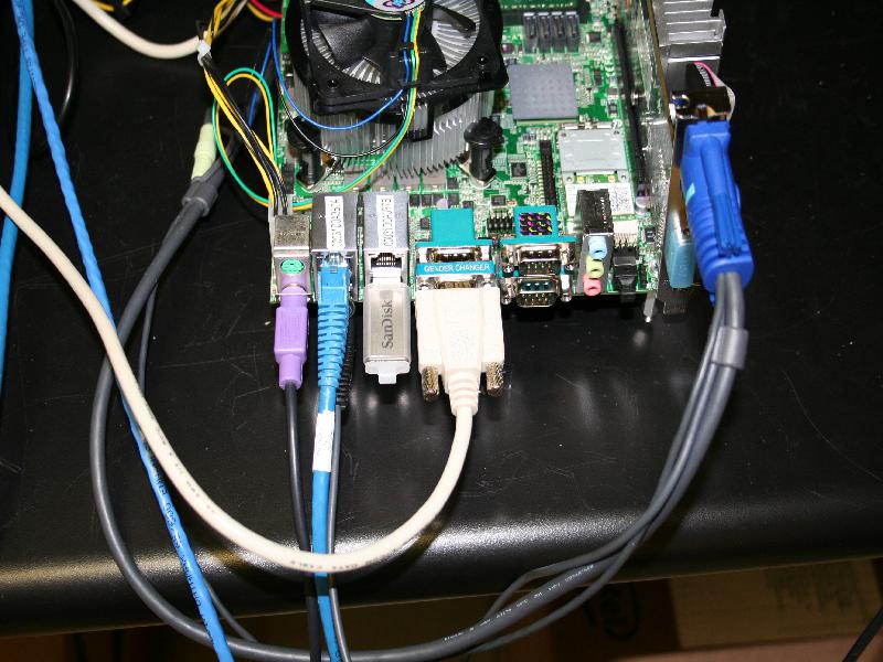
AttachVideo2.jpg
(99.6 KB
) - added by 15 years ago.
Attaching Video Cable and USB stick
-
EnableCruzer.jpg
(61.2 KB
) - added by 15 years ago.
Enable the SanDisk USB cruzer drive in boot menu
Download all attachments as: .zip
Note:
See TracWiki
for help on using the wiki.