
| Version 2 (modified by , 15 years ago) ( diff ) |
|---|
Assembling the LV-67C based Node
The assembling of new LV-67C based orbit node can be broken down into 4 tasks.
- Install Motherboard / Power supply
- Flash The LV67-C bios
- flash and install the CM3 module
- Install Disk and close case
How to Assemble the Case]
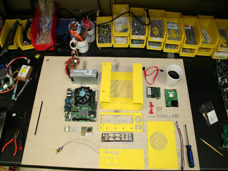
Components you will need to assemble a case:
System:
- 1 x LV-67C mother board
- 1 x 270 Watt power supply (Part Number FSP270-60LE)
- 1 x Sata Hard drive
- 1 x CM3
- requsite cables for CM3 and Hard drive
Case:
- 1 x case Chassis (U shaped chassis)
- 1 x rear face plate cap (Folds over the U)
- 1 x front face plate (has cm3 punch outs, and hard dive mount holes)
- 1 x top cover (has Circular CPU ventilation holes)
- 1 x motherboard face plate (supplied with the motherboard)
Fasteners:
- 4 x 6-32 ½" 100 degree screws for securing the motherboard
- 12 x 6-32 ¼" 100 degree screws for fastening the case together and securing the power supply to the case
- 1 x 6-32 ¼" pan head screw for fastening the power supply.
- 3 x 6-32 3/16" 100 degree screws for CM mounting to chassis
- 3 x 6-32 9/32" hex stand offs for CM mounting
- 3 x 6-32 3/16" pan head screws for CM mounting
- 4 x M3 5mm stand offs for hard drive mounting
- 4 x M3 5mm screws for hard drive mounting
Main U chassis:
- The mother board should come out of the static bag fully assembled. The orientation of the screw holes on the chassis is very specific. The Mother board should be aligned with the screw holes so that the headers point away from the vent hatching on the u channel. The portion of the chassis with the headers sticking out of it is the rear of the node. Once aligned use the ½" screws to secure the mother board
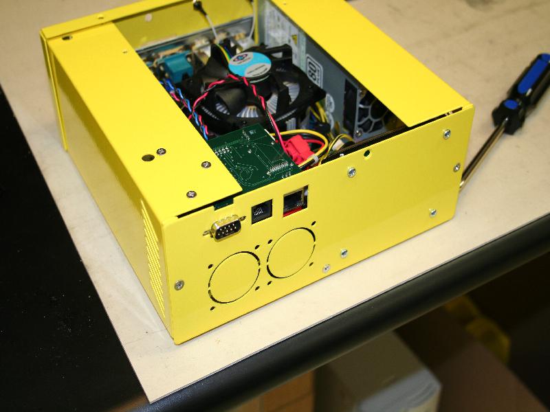
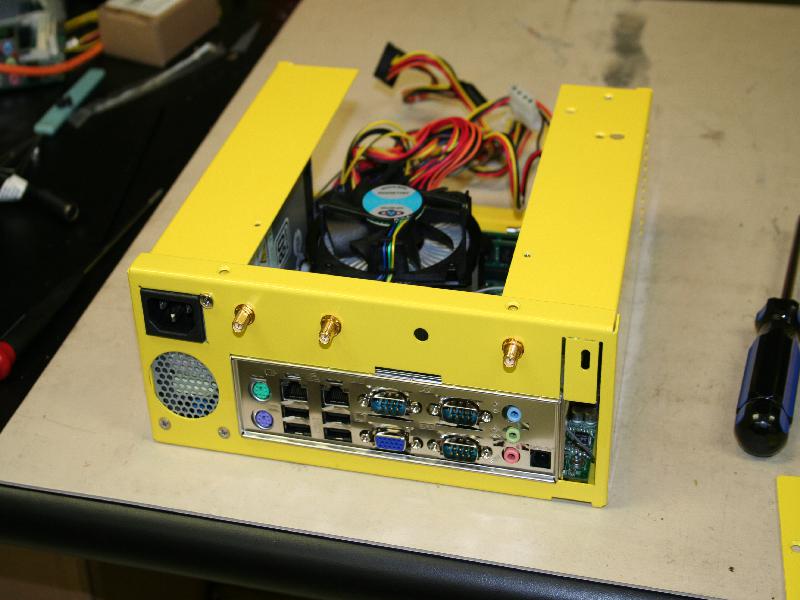
- The power supply sits in the open area to the left (looking at the rear) of the mother board. It will be secured to rear face plate when the it is installed. The power supply is not attached to the main U chassis however it must be inserted before installing the face plate. The power headers should be connected at this point. When sliding the power supply into place, separate the yellow/black 4 pin plug from the rest of the cables and thread it below the cpu heatsink (it's important to thread the wire below other wise it will get stuck in the cpu fan). Connect 4 pin plug it to the extra power header behind the PS/2 keyboard/mouse riser.
- Attach the mother board face plate to the opening on the rear face plate cap. It should be open on the right side (to allow for a expansion card) and closed on the left (as close to the power supply opening as possible).
- mount the rear cap on the U channel Chassis. Fasten it with 2 of the 6-32 ¼" 100 degree screws on the bottom. Next use two more of 100 degree screws and attach the bottom holes power supply to the rear cap. Use the 6-32 ¼" pan head screw to fasten the top of the power supply (near the 3 prong power header) to the rear cap
How to connect up power/disk headers and Flash The LV67-C bios
How to flash and install the CM3 module
How to install the Disk and close the case
Attachments (25)
-
AttachVideo.jpg
(115.8 KB
) - added by 15 years ago.
Attaching Video Cable
-
BackPlate.jpg
(71.3 KB
) - added by 15 years ago.
Installed Back Plate
-
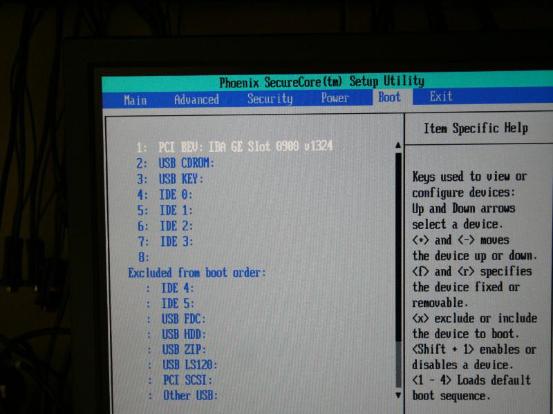
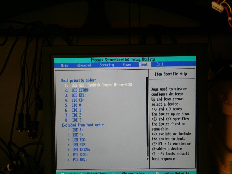
BootSequence.jpg
(77.5 KB
) - added by 15 years ago.
Bios Boot Sequence Screen
-
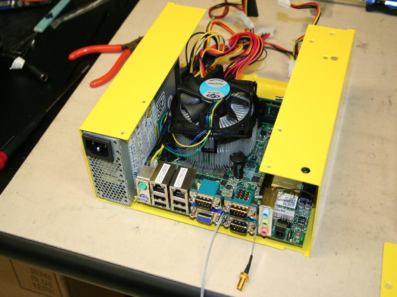
CasePowerMotherB.jpg
(91.1 KB
) - added by 15 years ago.
Mother Board and Power Supply Installed in U Channel
-
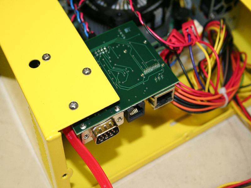
CmMount.jpg
(69.2 KB
) - added by 15 years ago.
Mounted CM
-
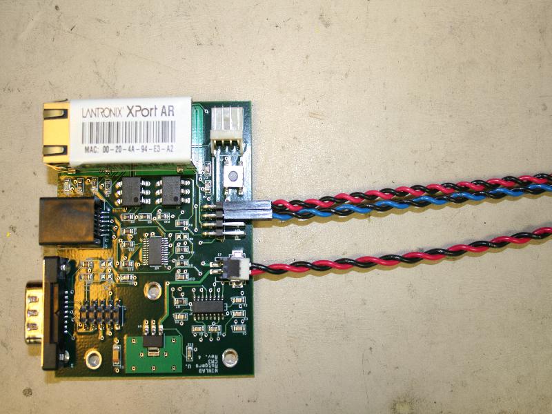
CmWire.jpg
(98.1 KB
) - added by 15 years ago.
Wiring of the CM
-
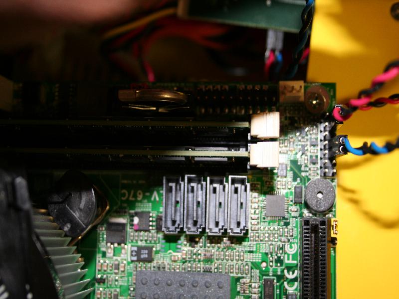
CmWireMotherB.jpg
(79.6 KB
) - added by 15 years ago.
Cm Wires attached to the motherboard
-
ComponentList.jpg
(103.2 KB
) - added by 15 years ago.
List of Components
-
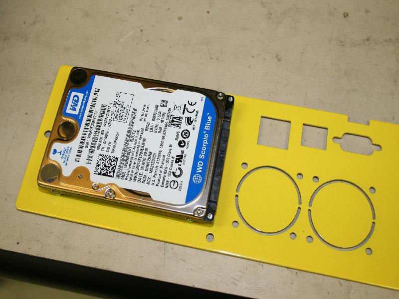
DiskBackPlate.jpg
(85.6 KB
) - added by 15 years ago.
Disk attached to Back Plate
-
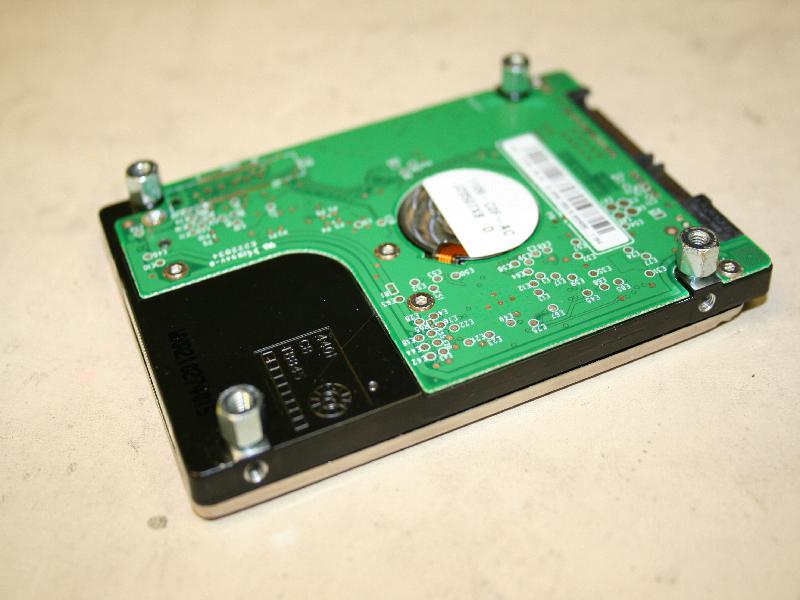
DiskStandOff.jpg
(65.6 KB
) - added by 15 years ago.
Standoffs mounted to disk
-
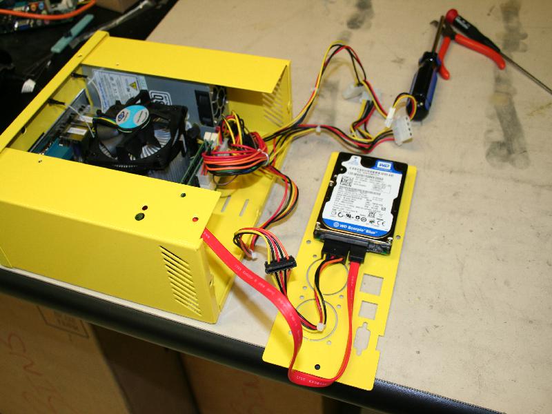
DiskWire.jpg
(84.8 KB
) - added by 15 years ago.
Wiring of Disk to Motherboard
-
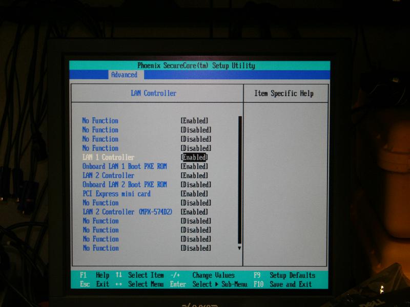
EnableLan.jpg
(63.8 KB
) - added by 15 years ago.
Enable the Lan Rom
-
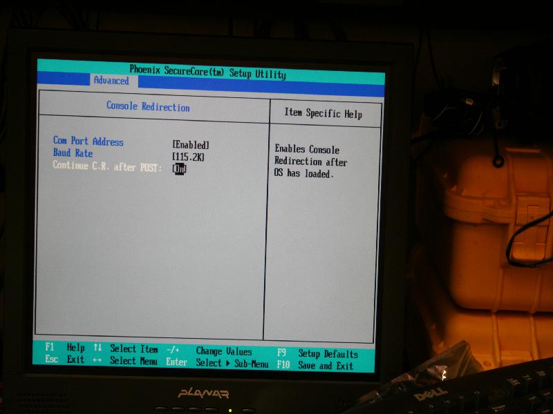
EnableSerial.jpg
(57.1 KB
) - added by 15 years ago.
Enable Serial Console Redirection
-
FrontFace.jpg
(74.1 KB
) - added by 15 years ago.
Attached Front Face
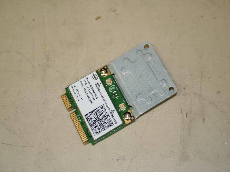
-
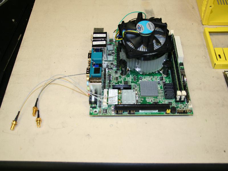
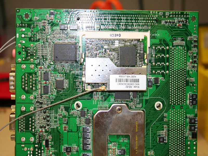
MBoardAssembled.jpg
(73.2 KB
) - added by 15 years ago.
Motherboards with Wireless Cards and UFL headers
-
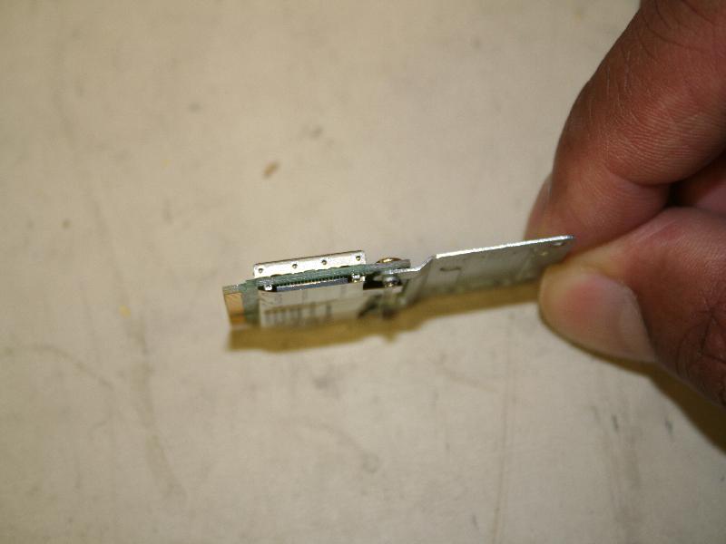
PciESide.jpg
(41.6 KB
) - added by 15 years ago.
Top profile of ½ Height Pcie Card with Extender attached.
-
PciETop.jpg
(64.8 KB
) - added by 15 years ago.
Side profile of ½ Height Pcie Card with Extender attached.
-
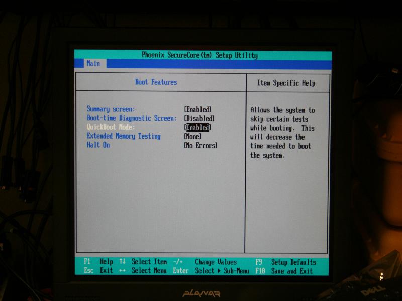
QuickBoot.jpg
(56.3 KB
) - added by 15 years ago.
Disable Halt on Errors
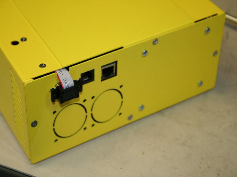
-
SerialBack.jpg
(45.9 KB
) - added by 15 years ago.
Serial cable attachment back
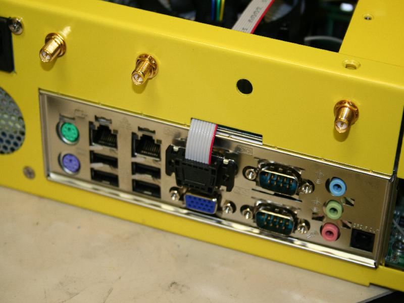
-
SerialFront.jpg
(69.5 KB
) - added by 15 years ago.
Serial cable attachment front
-
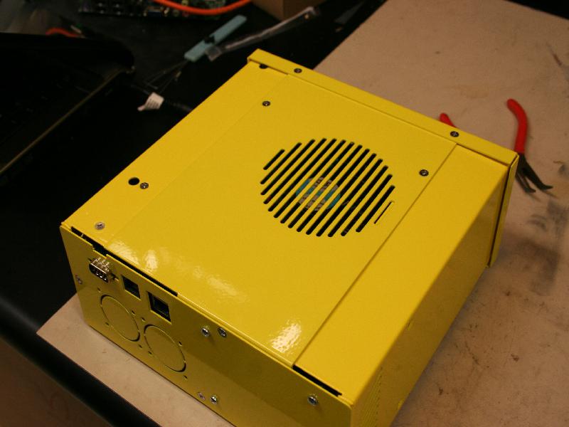
TopCover.jpg
(62.7 KB
) - added by 15 years ago.
installed Top Cover
-
UflAttachBottom.jpg
(173.1 KB
) - added by 15 years ago.
Attaching Bottom UFL cable
-
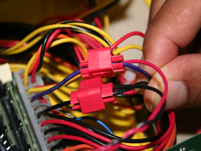
VampClip.jpg
(80.4 KB
) - added by 15 years ago.
Vampire Clips Installation
-
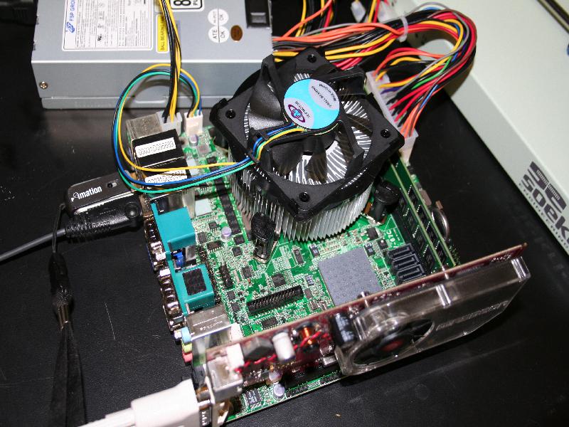
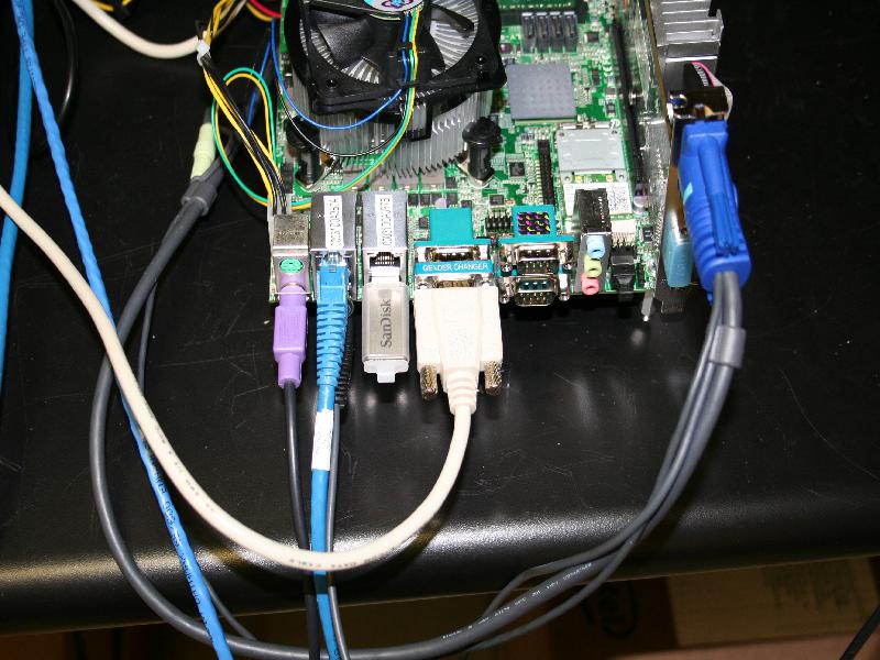
AttachVideo2.jpg
(99.6 KB
) - added by 15 years ago.
Attaching Video Cable and USB stick
-
EnableCruzer.jpg
(61.2 KB
) - added by 15 years ago.
Enable the SanDisk USB cruzer drive in boot menu
Download all attachments as: .zip
Note:
See TracWiki
for help on using the wiki.