
| Version 23 (modified by , 15 years ago) ( diff ) |
|---|
Assembling the LV-67C based Node
The assembling of new LV-67C based orbit node can be broken down into 3 tasks.
Flash The LV67-C bios
8/30/2011
We've simiplified the process a little with the usage of an bootable flash disk. There is also a slight change in the order of assembly because of an issue with CMOS reset after inserting new hardware.
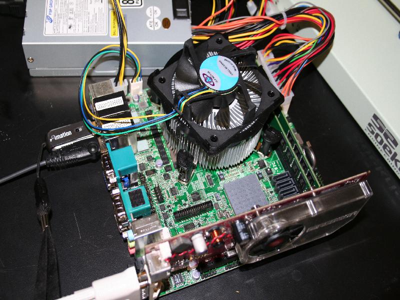
- After removing the lv-67c kit from it wrapping attach the pcm-cia and mini-pice cards (As below).
- Attach the video card assembly as prior
- Power On and listen for the post beep. Hit Delete immediately after. The screen setup will usually lag the input so you will have to hit the button before you can see the prompt.
- Once in the bios, goto the boot order menu and do the following:
- Disable the USB FDC: (select it and press x)
- Enable the USB HDDL SanDisk Cruzer Micro-(USB

- Save and exit
- After you save and exit the system will power down. If left alone it power back up and proceed to boot from the USB disk.
- After the post, in the serial console you will see the kernel boot messages pass by
- NOTE: The first time it boots from USB it will complain about the file system needing a check. Choose i to ignore this and let it finish booting.
- Once booted, login and issue a sudo poweroff command.
- remove the video card and replace it with the Ethernet card. Disconnect the KVM usb cables.
- Power up again, it should still boot into the serial console and you will eventually get to a login prompt.
- After logging in, issue this command
sudo nvramtool -B lv67c_2011-8-29.bios
- The bios is now configured. Reboot once more and check the serial console for bios boot messages. It should try to pxe from the leftmost interface (verify the mac address).

8/2011
The second batch of Lv67c motherboards do not need to have their bios flashed, only reconfigured.
- Attach requisite cables and Cards

- Serial Cable
- Video card with monitor cable attached (Do not use the onboard VGA)
- Ethernet cable into Leftmost port
- 24 pin and 4 pin power headers
- Keyboard
- Standoffs to prevent shorts
- Once the box has Posted (the beep) press delete quickly to get into the bios
- Adjust the following bios parameters
Main
->
 Boot Features
 ->->
   Halt on [No errors]
   Boot Time Diagnostic Screen [Disable]
Advanced
->
 Advanced Chipset Control
 ->->
   On Board Lan N Boot PXE Rom [Enabled]
->
 Console Redirection
 ->->
   Com Port Address [Enabled]
   Baud Rate [155.2K]
   Continue C.R. after Post [On]


 Note The N in Lan Rom refers to the Interface Number. If making a Gnu radio Node the device names will be shifted due to the additional NIC card. Thus the left most NIC will be eth1 which corresponds to Lan 1. If making a regular node then Lan 2 will be eth1 and only that rom should be enabled.
- Save these settings and exit. Once saved the node will power off and then back on again to "apply" the settings changes. You can unplug the node after the initial power off or let it reboot and then poweroff. You should be seeing output on the serial console now.
- Once powered off, remove the video card and attach the nic card (if needed). Connect the ethernet cable that carries Outdoor control vlan to the designated eth1 interface.
- Power on the node and hit del again to get back into the bios.
- If making a USRP node, in the boot menu choose the IBA GE slot 0100 v1321 boot item and exclude it from the boot sequence.
- Depending on node type you will see an item labeled IBA GE slot xxxx v1324. Where xxxx is the hex address for the device (e.g. 0900 for Lan 1). Set this device to be !#1 in the boot sequence. Save and exit.

- The node should now attempt to boot from pxe and if dhcp and tftp are setup correctly, the node should be able to boot into the pxe image.


6/2011
You will need the USB Thumb drive which has the bios and the utility to boot the motherboard from.
You will need a Video Card to flash the bios, the motherboard does not have one.
- Hit DEL key to get into BIOS
- change boot settings to boot of the USB Thumb drive.
- Reboot the Machine.
- Boot into the DOS shell.
- Change directory to bios
- Run plash16.exe bios.bak
How to flash and install the CM3 module
Flashing the CM can be done one of two ways
Flashing the CM over FTP
- Plug the CM3 into the network and power it on
- Find the IP address of the CM3 (whether it be already in DHCP or randomly assigned)
- ftp to the device
ftp xxx.xxx.xxx.xxx
- having some image "REV_X_Y_Z.rom.gz" use the 'put' command to flash the CM
put REV_X_Y_Z.rom.gz xport_ar.rom.gz
- if the image name is already xport_ar.rom.gz then there is no need to rename it. the image must be transfered to the device under than name or it will not be recognized as new firmware.
- The CM will not write the file and flash itself
- Flashing the device over serial
- Use a computer with "Lantronix Device Installer" installed on it.
- Go to 'Tools'→'Advanced'→'Recover Firmware' (or simply the F8 key)
- Configure the options, and hit OK to load the image
- Choose the COM port being used
- Select "Xport AR A1" as the device
- Make sure that the "Erase all flash" option is checked
- Enter the path of the image to be loaded
- The program will prompt you to power off the device, you can just ignore this and hit next
- The serial recovery will have started, but you must still power cycle the device before the transfer begins, either hit the reset button on the CM or just pull and reapply the power to the CM.
How to Assemble the Case
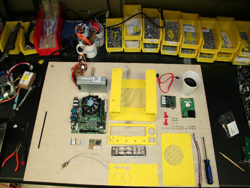
Components you will need to assemble a case:

System:
- 1 x LV-67C mother board
- 1 x 270 Watt power supply (Part Number FSP270-60LE)
- 1 x Sata Hard drive
- 1 x CM3
- requsite cables for CM3 ILYA FIX ME
- 1 x sata cable
- 1 x serial cable (from cm3 to motherboard)
Case:
- 1 x case Chassis (U shaped chassis)
- 1 x rear face plate cap (Folds over the U)
- 1 x front face plate (has cm3 punch outs, and hard dive mount holes)
- 1 x top cover (has Circular CPU ventilation holes)
- 1 x motherboard face plate (supplied with the motherboard)
- 1 x Velcro wire strap
Fasteners:
- 4 x 6-32 ½" 100 degree screws for securing the motherboard
- 12 x 6-32 ¼" 100 degree screws for fastening the case together and securing the power supply to the case
- 1 x 6-32 ¼" pan head screw for fastening the power supply.
- 3 x 6-32 3/16" 100 degree screws for CM mounting to chassis
- 3 x 6-32 9/32" hex stand offs for CM mounting
- 3 x 6-32 3/16" pan head screws for CM mounting
- 4 x M3 5mm stand offs for hard drive mounting
- 4 x M3 5mm screws for hard drive mounting
Wireless Adapters:
- 1 x minipcie Intel Wifi + Wimax 6250 card
- 1 x pcimcia Atheros Ar5212A 802.11 a/b/g wireless card
- 1 x minipice ½ height adapter
- 2 x minipice adapter screws (supplied with adapter)
- 3 x ufl-sma pig tails (9in)
Main U chassis:
- Assemble mini-pcie if necissary:


- There is a specific orientation for the ½ height adapter plate. If oriented incorrectly the card will not mount properly into the motherboard.
- Assemble the mother board:


- Attach the minicpie and pcimcia cards to the mother board.
- The mother board should come out of the static bag with cpu and memory installed.
- Connect all the pig tails and route the wires to the right side (facing the rear) of the motherboard.
- The Mother board should be aligned with the screw holes so that the headers point away from the vent hatching on the u channel.
- The orientation of the screw holes on the chassis is very specific.
- While aligning the mother board route the sma header from under neath the motherboard to the right behind the standoff.
- This keeps the sma-ufl wires away from the cpu fan.
- Once aligned use the ½" screws to secure the mother board.
- Attach the minicpie and pcimcia cards to the mother board.
- Install Power supply:

- The power supply sits in the open area to the left (looking at the rear) of the mother board.
- Separate the yellow/black 4 pin plug from the rest of the cables
- Slide in the power supply into place, while threading the black/yellow 4 pin header below the cpu heatsink.
- It's important to thread the wire below other wise it will get stuck in the cpu fan.
- The power supply will be secured to rear face plate when it is installed.
- The power supply is not attached to the main U chassis however it must be inserted before installing the rear cap.
- Connected the 24 pin atx power headers.
- Connect 4 pin plug it to the extra power header behind the PS/2 keyboard/mouse riser.
- Assemble the rear cap:

- Pass one end of the serial cable through the mother board face plate opening
- place the cable in the cut out on the top of the face plate opening.
- Attach the mother board face plate to the opening on the rear face plate cap, locking the serial cable into the designated opening.
- The face plate should be mount so that it is open on the right side (to allow for a expansion card) and closed on the left (as close to the power supply opening as possible). Install the end of the serial cable that is later attached to the CM at this time as well, as it gets threaded through the faceplate.
- Mounting the rear cap on the U channel Chassis:

- Fasten the rear cap with 2 of the 6-32 ¼" 100 degree screws on the bottom of the U chassis.
- Use two of 100 degree screws and attach the bottom holes power supply to the rear cap.
- Use the 6-32 ¼" pan head screw to fasten the top of the power supply (near the 3 prong power header) to the rear cap.
- Bolt all the sma headers to the face plate. The header position convention used is:
- Header 1 of the wimax card goes to the left most (closest to the power supply) hole.
- Header 2 immediately to the right of header 1.
- WiFi header of the 802.11 card goes to the right most hole.
- Wiring the CM:
- Attach the red and black power connector wires using the vampire clips to the purple and any black of the 24 pin ATX power supply connector respectively. See image below
 .
.
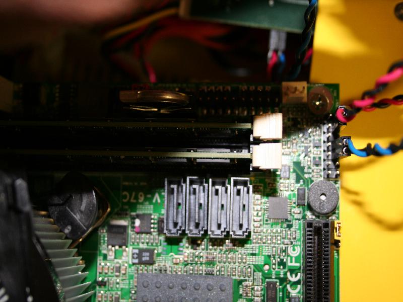
- connect the red/black twisted pair cable to the motherboard, and the other end to the CM as shown in the pictures below. Do the same for the blue/black twisted wire pair. The header on the MB is next to the RAM and SATA connectors.

- Attach the red and black power connector wires using the vampire clips to the purple and any black of the 24 pin ATX power supply connector respectively. See image below


- Mounting the CM:

- Attach the 3 6-32 hex stand offs to the cm card with the 3 6-32 pan head screws. the stand offs should be on the non-component side of the CM
- thread the other end of the serial cable between the 3 stand offs
- align the 3 stand offs with the 3 triangle oriented holes on the front left corner of the top of the U chassis.
- thread the other end of the flat serial cable (otherside should be going through slit on top of the face plate) in between the standoffs as to keep it in place and above the fan, them use the 3 3/16" 100 degree screws to attach the cm to the U chassis.
- Attach and Wire the hard drive:


- attach the M3 5mm hex stand offs to the hard dive using the bottom holes.
- Align the female end of stand offs with the holes on the right side of the front face plate (facing front)
- The face plate should be oriented so that the cm holes are in the upper left corner.
- The drive should be on the "inside" of the chassis and sata header should point to the left (towards the center of the case).
- Fasten the disk, stand off assembly to the face plate with the M3 5mm pan head screws.
- Attach power and sata cables to the drive.
- When attaching the sata cable to the mother board, use the header closest to the CPU (sata1)
- loop the velcro strap through the holes on the bottom:
- Tie down all the loose wires.
- This prevents stray wires from getting to close to the cpu fan.
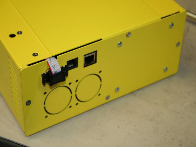
- Mount the rear face plate:

- Use the three 6-32 ¼" 100 degree screws to attach the front face.
- use only the 2 side and bottom screw holes
- the top of the face plate will be attached to the top cover
- Use the three 6-32 ¼" 100 degree screws to attach the front face.
- Attach the Top Cover

- Use the remaning screws to attach the top cover.
- The rear of the top cover should go below the cap.


Attachments (25)
-
AttachVideo.jpg
(115.8 KB
) - added by 15 years ago.
Attaching Video Cable
-
BackPlate.jpg
(71.3 KB
) - added by 15 years ago.
Installed Back Plate
-
BootSequence.jpg
(77.5 KB
) - added by 15 years ago.
Bios Boot Sequence Screen
-
CasePowerMotherB.jpg
(91.1 KB
) - added by 15 years ago.
Mother Board and Power Supply Installed in U Channel
-
CmMount.jpg
(69.2 KB
) - added by 15 years ago.
Mounted CM
-
CmWire.jpg
(98.1 KB
) - added by 15 years ago.
Wiring of the CM
-
CmWireMotherB.jpg
(79.6 KB
) - added by 15 years ago.
Cm Wires attached to the motherboard
-
ComponentList.jpg
(103.2 KB
) - added by 15 years ago.
List of Components
-
DiskBackPlate.jpg
(85.6 KB
) - added by 15 years ago.
Disk attached to Back Plate
-
DiskStandOff.jpg
(65.6 KB
) - added by 15 years ago.
Standoffs mounted to disk
-
DiskWire.jpg
(84.8 KB
) - added by 15 years ago.
Wiring of Disk to Motherboard
-
EnableLan.jpg
(63.8 KB
) - added by 15 years ago.
Enable the Lan Rom
-
EnableSerial.jpg
(57.1 KB
) - added by 15 years ago.
Enable Serial Console Redirection
-
FrontFace.jpg
(74.1 KB
) - added by 15 years ago.
Attached Front Face
-
MBoardAssembled.jpg
(73.2 KB
) - added by 15 years ago.
Motherboards with Wireless Cards and UFL headers
-
PciESide.jpg
(41.6 KB
) - added by 15 years ago.
Top profile of ½ Height Pcie Card with Extender attached.
-
PciETop.jpg
(64.8 KB
) - added by 15 years ago.
Side profile of ½ Height Pcie Card with Extender attached.
-
QuickBoot.jpg
(56.3 KB
) - added by 15 years ago.
Disable Halt on Errors
-
SerialBack.jpg
(45.9 KB
) - added by 15 years ago.
Serial cable attachment back
-
SerialFront.jpg
(69.5 KB
) - added by 15 years ago.
Serial cable attachment front
-
TopCover.jpg
(62.7 KB
) - added by 15 years ago.
installed Top Cover
-
UflAttachBottom.jpg
(173.1 KB
) - added by 15 years ago.
Attaching Bottom UFL cable
-
VampClip.jpg
(80.4 KB
) - added by 15 years ago.
Vampire Clips Installation
-
AttachVideo2.jpg
(99.6 KB
) - added by 15 years ago.
Attaching Video Cable and USB stick
-
EnableCruzer.jpg
(61.2 KB
) - added by 15 years ago.
Enable the SanDisk USB cruzer drive in boot menu
Download all attachments as: .zip
Note:
See TracWiki
for help on using the wiki.