
Table of Contents
OTG Software Architecture Design
Zhibin Wu
Introduction
The ORBIT Traffic Generator software is designed for the sole purpose of using on NSF ORBIT Testbed. It is a typical application of ORBIT Testbed. ORBIT Traffic Generator is a special tool for experimenters to generate traffic for testing network performance. Its primary focus is to generate bulk data of various characteristics and use either TCP or UCP protocol to transport data. ORBIT Traffic Generator Software consists of two components. One is the OTG (ORBIT Traffic Generator); the other is OTR (Orbit Traffic Receiver). They are used in pair to transmit and receive data respectively. The OTG software has a flexible design to support various configuration of generators such as CBR and exponential on/off traffic.
Summary of Major Design Requirements
ORBIT Traffic Generator Software consists of two components. One is the OTG (ORBIT Traffic Generator); the other is OTR (Orbit Traffic Receiver). The OTG is running on a sender node and OTR is running on a receiver node. The Hardware platform for the software is ORBIT nodes. Each ORBIT node is a micro-computer with Linux Operation system. Nodes are connected like a grid with wired or wireless communication links.
The OTG software must support various TG (Traffic Generator). TG is regarded as a replaceable sub-component of OTG. TG Structure should be kept as simple as possible to let the user design custom TG conveniently.
General Approach
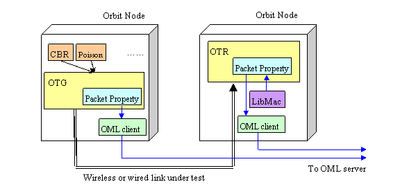
Design Diagram

Figure 1. Design Diagram
A very important motivation and feature of ORBIT Traffic Generator design is its integration with the OML (''ORBIT Measurement Library'') framework. The properties of each packet generated or received such as packet size, packet deliver time are all reported to OML by OTG and OTR. Users can calculate certain measurements like throughput, delay by either applying special OML filters or querying the OML database directly. There also exists an interface to use LIBMAC to correlate each packet with corresponding physical layer parameters. The design complies with modular principle and different modules are kept loosely coupled. The interface to the OML, the interface to the user are supposed to be dynamically generated from an ORBIT application definition file. Both of them should be independent with the core module of application. TG and OTG are integrated through a simple standard interface. The whole software is designed by OOP (Object-Oriented Programming) Method with C++ language.
Overall Design
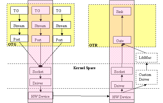
Software Architecture Diagram

Figure 2. Software Architecture Diagram
The OTG and OTR program are implemented in the user space. To support point-to-multipoint communication, each port in OTG could associate more than one stream object. Based on different source and destinations, packets are classified to several streams. A port in OTG could deliver several streams to different OTR program through a common UDP or TCP port. Also, the OTR could receive several streams from different OTG program. To let the receiver software OTR have the capability to extract PHY measurements from the driver, we need a custom driver which is compatible with LibMac library. The above mentioned architecture allows us to extend the OTG-OTR application to support multiple sending streams and multiple receiving applications. However, the baseline requirement for the OTG/OTR design is the very simple one-sender-one-receive point-to-point communication. Therefore, the baseline application will only include a communication path and components in the shaded region. And this case will also satisfy the test and measurement demands of most users.
Note that in OTG and OTR, "Stream" and "Gate" are master components respectively. They control the sending and receiving thread respectively.There also exists an OMLObject pointer in Gate and Stream to enable control of OML measurements reporting.
Design of OTG
The OTG is a multi-thread application. The main thread is used to handle run-time user-input. For each stream, a separate thread is created for sending a stream to the corresponding application of another node. Each stream thread performs a while loop to conduct following operations:
- Load a packet from the "TG"
- Wait till the "time to send" of this packet
- Send the packet through the "Port".
Each "stream object" is uniquely bound to a TG object and Port object. That is to say, one Port is only used for sending one stream. But one OTG application could have multiple streams, thereby using multiple ports and multiple TGs. From above we can see that the Stream object is the master object controlling other two objects: TG and Port, which both are passive and would be only used when the interface functions are called. Note that this architecture design allows one OTG Application having multiple streams. In practice, however, the user is now limited to start only one stream with one OTG application.
Design of OTR
The OTR is a multi-thread application too. The main thread is to handle user input. And for each Gate object, a separate thread is going to create to receive packets from this gate. Each Gate object is the master object to control other objects in the OTR program Whenever an OTR application is started, at least one Gate has to be started as default. However, a gate is not limited to receiving homogeneous packets from the same source. If multiple sources or connections are communicating with one socket port, the Gate will demultiplex the traffic and give each packet a flow identifier to show its source address. However, all packets are still passed to the same Sink object. When an OTR application is started, a default gate will be created. A default sink object is also created to bind to this gate. In the case of UDP, whenever a packet from a new address, it will generate a new flow for all packets from this address. In the case of TCP, whenever accept a new connection; a new flow is created to accommodate the packets in this direction. Note that this architecture design allows one OTG Application having multiple Gates. But in practice, the user is now limited to start only one Gate with one OTR application.
Component Design
Stream, Port, TG, Gate and Sink are key components of the core module of OTG and OTR.
TG
TG (Traffic Generator) is the entity which supplies packets to be transmitted. The OTG software support multiple types of traffic generators. TG is the source of packet. TG is designed as a complete passive object which is driven by the request of Stream Object. The TG generates a packet stream with a certain packet size distribution and a certain packet interval distribution. The contents of the packet are usually unimportant and would be randomly filled. Also, the TG object has a function to fill the payload with certain content which is suitable for extending the OTG program as an FTP application.
The standard interface between TG and OTG is a member function of the Generator class called “nextPacket (Packet *p)”. Whenever the main thread of OTG uses this function, a packet object is passed as the input parameter. And in the instantiation of this function, the generator should fill the packet size and timestamp of this packet object.
Port
Port object is designed as a sending communication interface of the application. Port only functions a sender. Each port is controlled by a Stream object. A variety of Port objects are supported based on the supporting protocol. Currently, we have three protocols supported: UDP, TCP, Ethernet RAW sockets.
Stream
The introduction of the “stream” object is to use a common class to control different type of TG and Ports. Each Stream is designed like a packet queue which connects the TG and Port. But it only holds one packet. It generates one empty packet structure for TG. Once TG feed this packet with payload and other packet-delivery information, the packet is stored in the stream. This packet will be given to Port for transmission according to the deliver time property of this packet.
Gate
Gate object is designed as a receiving communication interface of the OTR application. The name Gate is named as a counterpart of "Port". In other words, Gate is "receiving Port" to handling reception. Basically, we have two working modes for a Gate: w or w/o libmac support. With Libmac support, the OTR program cold extract some PHY layer parameters. A variety of Gate objects are supported based on the supporting protocol. Currently, we have three protocols supported: UDP, TCP, Ethernet RAW sockets.
In General, the gate conduct following operations for each incoming packet.
- receive through socket interface.
- demultiplex (getting the source information)
- post-process (set some properties)
- sink report measurements and dump the packet.
- pass to sink object for dumping
The demultiplex part of UDP Gate and TCP Gate is slightly different:
- UDP Socket create a new flow based on the received packet's source address if necessary. therefore, we use simple consecutive numerical numbers as flow id.
- TCP Socket would create a new flow when acceptNewConnnection() function is called. This occurred before a single TCP packet is received. We use socket file descriptor as flow id.
Note: We did not support demultiplexing for raw sockets now
Flow
Each gate holds a flow table to record the demultiplex information. It says which packet is from which source IP and port. Unlike previous design, the packet is no longer passed to the flow object, but from gate to sink directly. Flow table is just an index table to checking the packet's srouce information and set the "flow id" measurement for this packet. The information in the table should include:
- flow identifier
- sender IP address
- sender port (if applicable)
- sender MAC address (if applicable)
Sink
Sink is dummy. Just dump every received packets to nowhere.
User Interface
The ideal design goal for user interface is to let this part should be automatically generated by an application interpretation engine. When this engine is feed with the application definition file, C source codes will be generated and compiled with other parts of this program.
Currently, the interface is handled by an extension of POPT utility.
Command-line Input to start the program
The basic format for user to specify an option is “—option [arg]” format. Because we have multiple kind of protocols and generators to support, the commands to configure the OTG program and OTR program need to first figure out those type information. After that, further command-line options about that specific generator and protocol-port could be parsed further. However, the user only need to give all options in one command line. The program will automatically parse them in this 2-tier manner.
Select Protocol and Generator Type
The “parseOptionsPhase1” function in the main program (otg.cpp & otr.cpp) is in charge of parsing the necessary protocol and generator types. After parsing that, a specific generator and port will be created.
Get 2nd Tier Option
The “parseOptionsPhase2” function in the main program (otg.cpp & otr.cpp) is in charge of getting and parsing the protocol and generator options.
Run-time Commands
Program Termination
The OTG and OTR program is not controlled by pre-defined test duration. Instead, it has to be terminated by the “exit” command. As long as the command is not given, the OTG will keep pumping traffic and OTR program will keep receiving incoming packets.
Pause & Resume
The design for user run-time pause and resume is to be handled by the Stream object. The Stream will pause its clock and stop loading packets from generator whenever a "pause" command is given by user.
Change TG Parameters in Run-time
Help information
Usually, —help should list all available options. But with current POPT package we cannot produce “help” information for unknown port type and generator types. So, simply type “—help” wll not give all possible options, but only the [protocol][generator] options.
Measurements
Measurement are generated within the OTG and OTR software and reported to a library server in ORBIT testbed throughput the “OML” architecture. In brief, the measurements are collected by each OML client in every running node and sent to a collection server. If an application wants to use OML, the application has to first call a “init_oml” function. Then add different measurement-points in the application where a measurement is triggered, anther OML function has to be called. Finally, those measurements will appear as records in an OML databases.
Per-Packet Measurement
There are a lot of measurements are associated with a single packet.
- Packet Generation Time
- Packet Transmit Time
- Packet Receive Time
- Packet Size
Measurement are generated within the OTG and OTR software and reported to a library server in ORBIT testbed throughput the “OML” architecture. In brief, the measurements are collected by each OML client in every running nodes and sent to a collection server.
Per-Stream Measurement
For each stream generated by OTG, a stream id and pkt number is stamped in the payload of the packet. And those information could be retrieved by OTR. Also, the OTR could demultiplex all receiving packets and put them in different flows. So, there are 4 measurements corresponding to this:
- packet sequence number from sender side
- Flow id from receiver side
- Flow packet number
Physical layer measurements
With the help of LibMAC, two physical layer parameters could be extracted from a custom driver:
- RSSI: Received Signal Strength Index
- TxRate: Xmit rate indicated in the Signal Field of PLCP header of received packet. for example 55 indicates 5.5Mbps, 540 indicates 54Mbps.
Measurement Reporting Triggers
The OTG has one measurement reporting trigger and OTR has two measurement reporting triggers. In OTG, measurement will report when the Stream is going to call Port→sendPacket()function). It will trigger reporting of four measurements:
- pkt_seqno
- pkt_size
- gen_timestamp
- tx_timestamp
In OTR, measurements will report by the Gate object whenever a packet is processed. Six measurements are triggered:
- pkt_seqno (stamped in sender side)
- flow_no:id of the flow
- rcvd_packet_size: Received Payload size of the packet
- rx_timestamp: Time when packet is being received
- rssi:
- xmit_rate
Another measurement table is also created by OTR using oml_newflow() call for demultiplexing receiving packets.
- flow id
- sender ip
- sender port
Fault Management and Exception Handling
Basically, information of every critical exception is put into stdout if the program is going to abort. The information is output by an "throw" operation. and the main program will eventually output it in STDOUT. However, it seems only the function in the first-tier of main program could throw it correctly and the main program will output it into STDOUT, for those functions referred deeper, we see
terminate called after throwing an instance of 'char const*'
Aborted
This part needs to be discussed further.
See Also
- Understanding OTG Main Program
- Understanding OTR Main Program
- Function Specification: Writing New Traffic Generators
- Function Specification: OTG/OTR with OML Integration
- Function Specification: User Interface Design
- Function Specification: Interfacing LIBMAC
- Function Specification: Port
- Function Specification: Gate
- Function Specification: Stream
- Function Specification: Timing Control
Attachments (2)
- SoftArc.gif (9.1 KB ) - added by 21 years ago.
- OtgDesign.gif (5.5 KB ) - added by 21 years ago.
Download all attachments as: .zip